This page contains some of the more useful formulae used in radiocommunications work.
Free Space Loss
Free Space Loss = 32.4 + 20log(d) + 20log(f) (dB), Where d is the distance in km and f is the frequency in MHz Free Space Loss = 92.4 + 20log(d) + 20log(f) (dB), Where d is the distance in km and f is the frequency in GHz andElectric field strength E = Pt - 20 log (d) + 74.8 (dBuV/m), Power Flux Density PFD = Pt - 20 log (d) - 71 (dBW/m2), Where Pt is the transmitted EIRP in dBW, E is Electric field Strength in dBuV/m (Note 1V/m = 120 dBuV/m) and d is the distance in km |
Dish Antennas Gain G = 4p Ae / l2 where Ae is the effective area Ae = n x A n = illumination efficiency and A = pD2/4 where D = dish diameter. Beamwidth This is related to the gain. For a circular dish, the half power beamwidth in the Electrical plane is qE = 73l / D. A useful approximation where the half power beamwidth is expressed in degrees gives the gain in dB:
Focal length of parabolic dish This only works for prime focus dishes but can be useful. Measure the diameter of the dish, call this value D. Then measure the depth of the dish, the distance from from the plane of the rim to the centre and call this value d. Then:
Focal point of a parabolic satellite dish
|
|
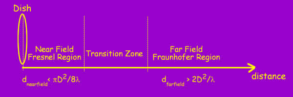
Far Field/Near Field
Aa antenna is not a point source of radiation and this has to be taken into account when calculating the field strength at a distance from the antenna. At large distances, a dish may be considered as effectively equivalent to a point source, this is the far field. In the far field, the wavefront can be considered to be planar with E and H field vectors normal to the direction of propagation. Close to the dish is the near field region, where evaluating the E and H fields is more complex. The transition from near field to far field is not sharp, however the near field for a parabolic antenna is generally considered to extend out to the distance:
Where D is the dish diameter and l the wavelength. Some figures may be of interest, at 10GHz with a 1m dish, the far field distance is 70m. |
|
RF Exposure At the inner edge of the far field region of a dish, the power flux density (PFD) for a transmitted power P may be calculated from the above equations:
The situation in the near field is more complex. This is a pity as that's often where we have most interest. How the power flux density varies in the near field depends on how the dish is illuminated and it's shape. Typically professional dishes will be circular and desiged with an illumination taper to 10% at the edge of the dish. For modelling the illumination has been approximated as a function of the radial distance
Getting a result generally requires a computer simulation. See NTIA Report 87-129 for detals. The NTIA report suggests calculating with a correction factor based on a multiple of the feild strength at the far field boundary 2D2/l. This method only works for circular apertures on-axis. Off-axis levels will be lower and can be estimated. Non-circular apertures can be treated with a similar methodolgy. The peak value of the correction factor depends on the value of n, getting higher and closer for higher values of n. e.g. 25 for n = 0, ~40 for n = 1, ~100 for n = 2. Dishes with values of n below ~1.5 show oscillations in the correction factor. The correction factor also depends to an extent on how large the dish is in terms of wavelengths. For a dish antenna > 20l, with n = 1, the variation in near field power density with distance and normalised to unity at the edge of the far field has been modelled as:
When using this to work out exposure limits the maximum value of the correction factor is taken as a worst case, even for locations closer to the dish.
In this example, that occurs near X = 0.1, which is 10% of the far field distance with the correction at this point equal to 41.3
times the far field boundary field strength.
Don't get too precise with this number as it does depend on how the dish is illuminated.
Many dishes will be lower. It can be taken as a guideline. |
TV Stuff - note historic interest, this is well out of date TV Channels The band used in the UK is UHF channels 21-68. These channels are each 8 MHz wide covering 470 MHz to 860 MHz. You can calculate the frequency of a particular channel using the formula: Frequency (MHz) = 303.25 + ( 8 x Channel Number ) UHF TV Aerials Aerials are commonly sold with their performance optimized for one of
6 groups of channels. Often the end cap is colour coded to indicate the
channel group:
Choosing a channel for a VCR/STB If you need to use an RF link to connect a VCR or set top box or video game to your television, choosing the correct output channel is not as simple as it used to be. In the old days, Channel 36 was often used as this was not used by the boradcasters. Since Channel 5 and the new digital services now do use this channel another channel sometimes has to be selected. If you tune the video or set top box to a random clear channel you may find wavy lines or worse across another analogue channel, or lose reception from a digital channel. The reason for this is complicated, depending on the design of the television tuner. There are some combinations of channels that should be avoided when selecting a channel for the VCR/set top box output. These channels are easily calculated. If channel N is in use, channels N, N+5, N-5, N+9 and N-9 should not be used. Adjacent channels N+1 and N-1 should also be avoided. The channels that should be checked are all those used by transmitters in the area, including digital channels even if you do not have a digital receiver. As in many areas, there are now 10 or more channels used, it may be hard or impossible to find a good channel to use. In these cases, a compromise will have to be reached.
An example Around Oxford the following channels are used: The channels that can also not be used are therefore: N-9 25 38 39 40 43 44 45 46 51 54 58 59 Leaving: 21 22 23 24 26 27 28 30 31 32 33 35 36 37 41 50 64 Avoiding adjacent channels leaves: 21 22 23 24 26 27 28 30 31 32 36 37 41 50 Quite a good choice - it looks carefully planned, and indeed it was. If channel 36 is chosen for the VCR, channels 37 and 41 are unavailable, leaving plenty of choice. However, many of the seemingly clear channels are used by nearby transmitters narrowing the choice. |
© Mike Willis 23rd April 2005