
Some construction projects designed in KiCAD - to be extended.
Many of these projects use the Arduino familiy of microcontollers and you will need use the Arduino IDE, possibly install some libaries and perhaps make simple changes to the code for configuration. If you don't know the basics of programming, while it is never too late to learn, these are probably not projects for you. I can't offer hand holding level support, so please don't ask.
These projects use surface mounted devices(SMD). I try to use the larger sizes, but don't be afraid of SMD as once you get used to them, with the right technique, I find them easier to work with than through hole parts, not least because you don't have to work on both sides of the PCB. If you find them too small to see, then use magnification. As we get older we find it harder to focus, a set of strong reading glasses, a dioptre or two stronger than you need for reading can help enormously for close SMD work and is much easier than trying to use a microscope. It probably won't be long before you start needing magnification for through hole parts as well, so best get the experience now. The good news is your fine control in manipulating parts with tweezers benefits from the magnification. It is a feedback loop.
Another tip for making neat SMD solder joints is to get hold of some 0.3mm solder and a fine tip temperature controlled iron.
The Gerber files are used for manufacturing PCBs. There are several suppliers on the web, you simply upload the zip file to their web server, select how many you want, the board type and thickness (FR4, 1.6mm), the number of layers (usually 2) and if you like a solder mask colour, and they do the rest. I have used JLCPCB and PCBWay successfully
Arduino based antenna Switch ControllerI have been frustrated with the lack of antenna outputs on my Icom IC-7300 for a while. I have a relay based antenna switch but it needed to be manually controlled and I wanted to automatically select an antenna depending on the band in use. Ideally changing the antenna configuration should not require re-programming. I also needed a band select for a linear amplifier, which is essentially the same function when you take away the relays.
When I got an Icom IC-705, I needed to control the filter bank in an HF linear amplifier I was building. The IC-705 does not have a CI-V port but does provide CI-V data over Bluetooth. Compatible Bluetooth serial data modules are readily available at low cost so a header for these has been included as an option. Alternatively, this header could be used for RS232 TTL.
The Yaesu FT817 and some other radios use a voltage output to indicate the band. The Elecraft K3 provides band data as four TTL level signals on an accessory port. This allows the selection of up to 16 bands. Both of these input methods only indicate the band, not the specific frequency or mode in use, but can still be useful for selecting antennas.
Rather than develop a different PCB for each band indication standard, I developed a more universal board and Arduino firmware.
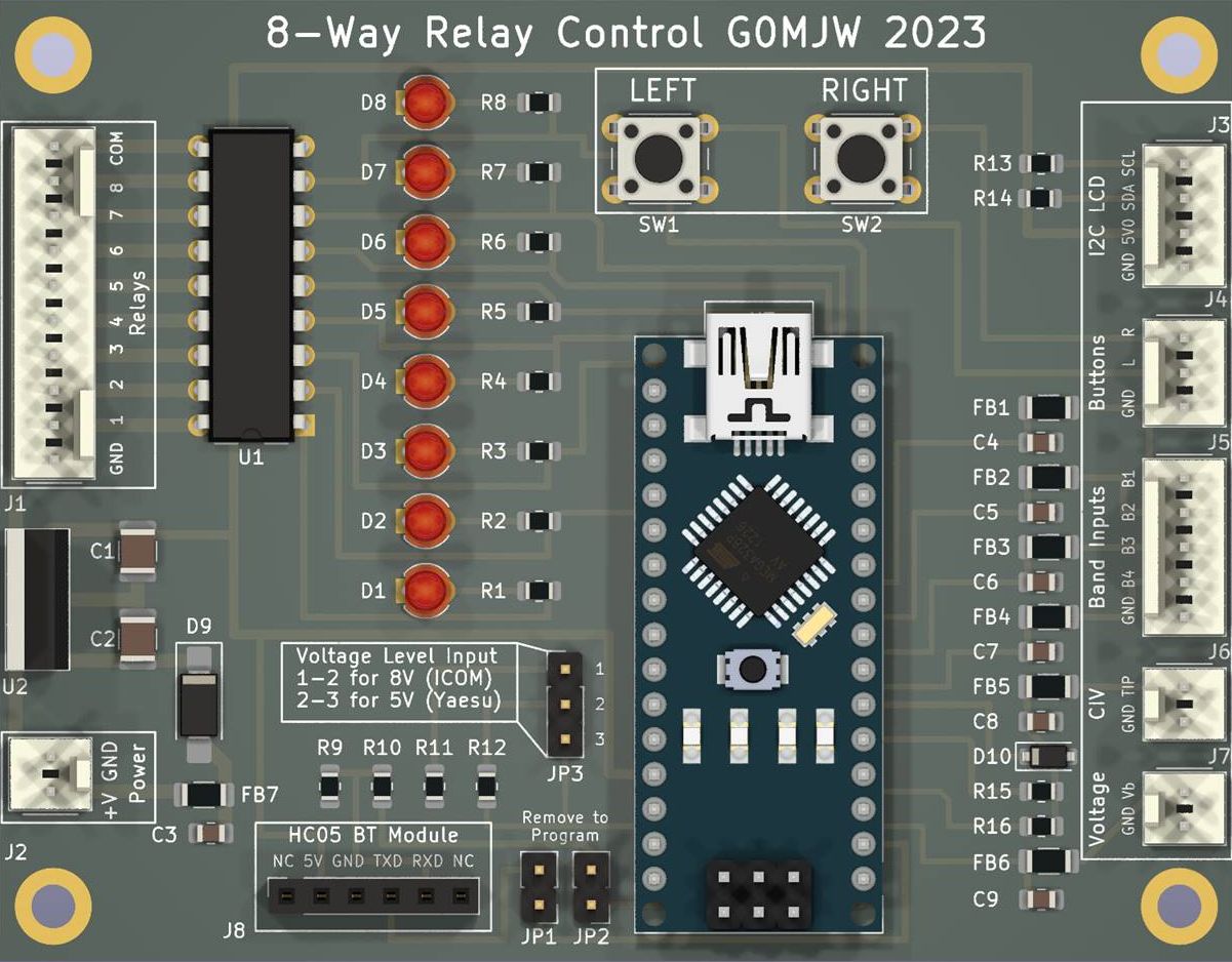
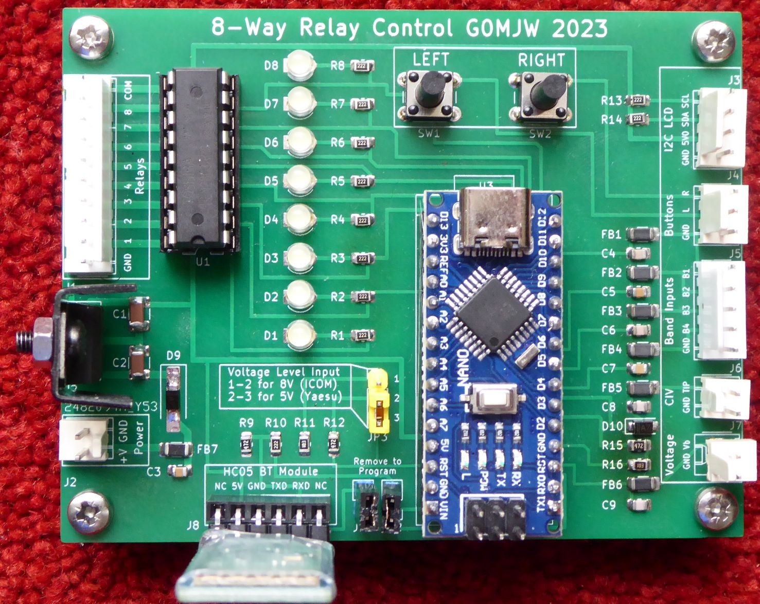
The PCB designed to take the frequency / band data from common radios and use it to select from up to eight antenna relays. Interfaces supported include Icom C-IV, Band Voltage, 4-bit band data and C-IV over Bluetooth. See the article linked below for more info.
The firmware is written in the Arduino IDE in C++ with configuration in a header file "definitions.h". It uses a two-button menu system. A short press on the left button changes to the next antenna relay down and a press on the right button select the next antenna relay up. The selection is stored in EEPROM so the switch will remember to it when that band next is selected, even after power cycling. At power on, a long press of both buttons enters a configuration mode. The left button cycles through menus, the right button selects. This allows setting the detection mode, the CI-V address, if used, and several other options, including a reset to defaults.
PDF Article Gerbers Arduino Software 3D Printable enclosure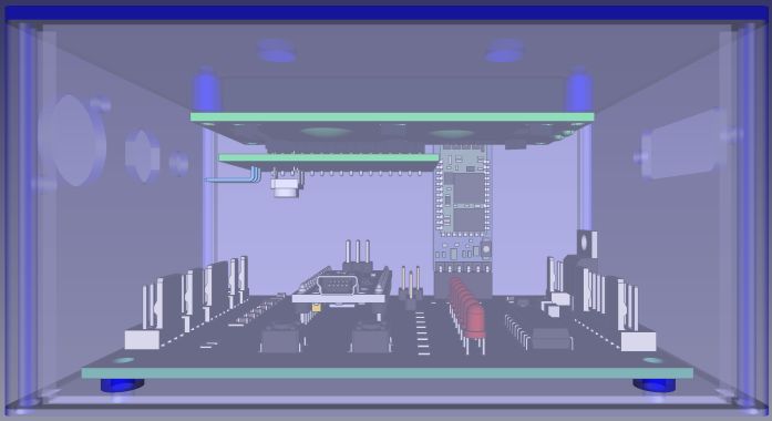
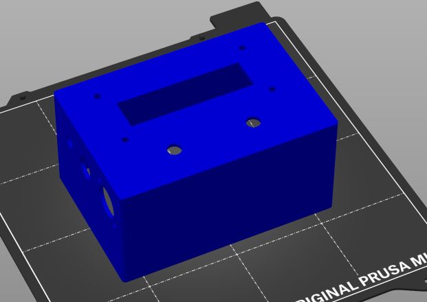
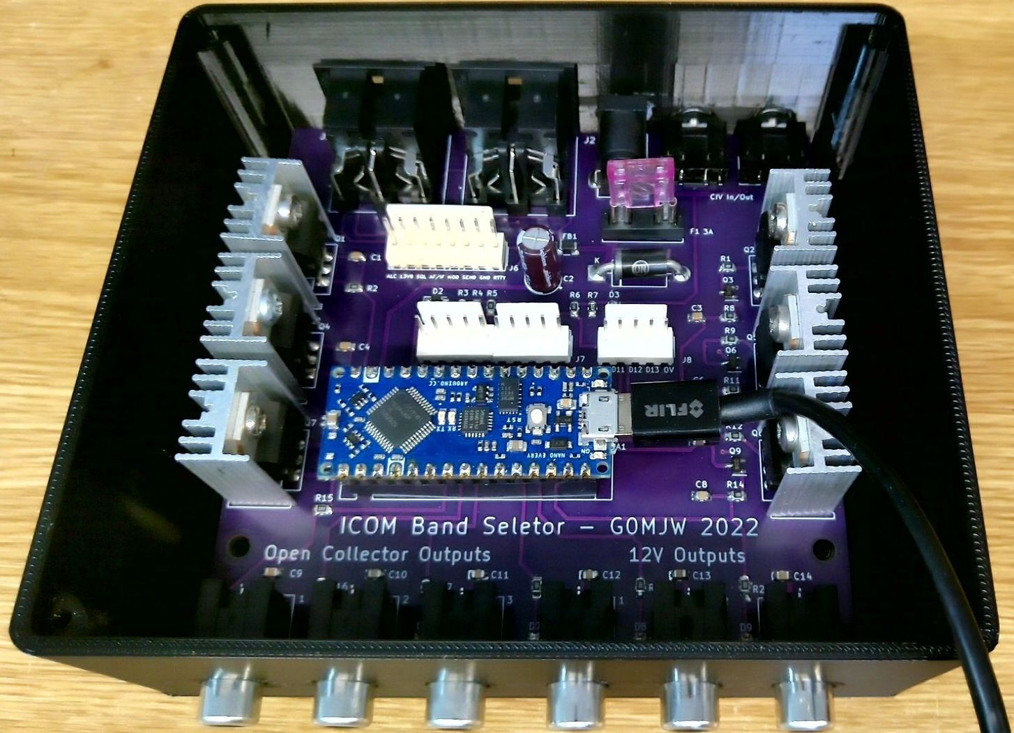
The 3D case is designed to fit the PCB is a relatively small space. The connector holes fit a standard panel mounting DC jack socket type DC-022 for the power, a standard 180 degree 5 pin DIN for the Band signals and a 3.5mm jack socket for the C-IV or Band Voltage (I figured nobody would need both at the same time), and a DB15 socket for the relay lines (this is the two row version, not the compact 3 row type commonly used for VGA). The holes for the push buttons are 7mm.
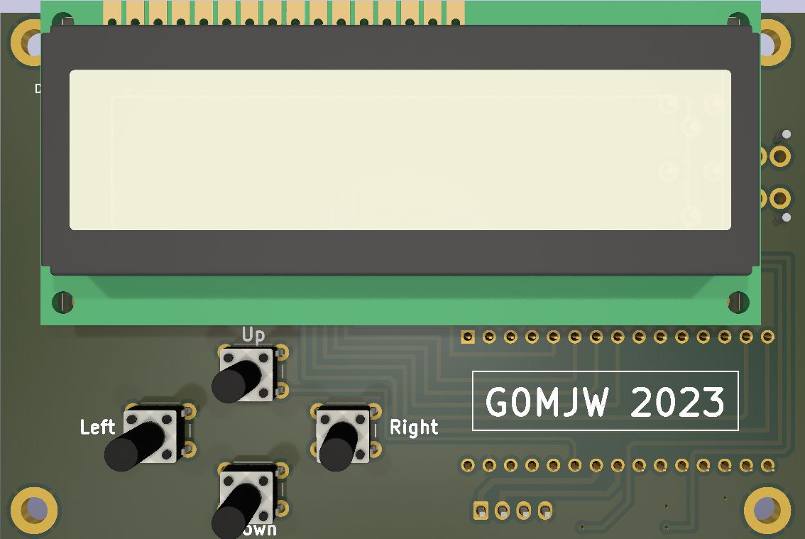
K3NG Arduino based Rotator Controller PCBThis is a PCB for K3NG's rotator interface intended for Yaesu rotators with a built in control interface, e.g. the G-2800DXA/G-1000DXA/G-450DC/G-5500DC/G-800DXA series. Not other rotators, though you could connect relays with protection diodes to the outputs - see K3NG's manual. The I2C interface is available if you wish to use it with 7 segment displays etc.
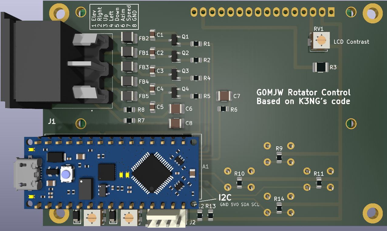
The software for this is on K3NG's github site. It requires configuring, instructions are provided, you will need to configure the Arduino pin mapping, which you can find from the schematic, in the software. This idelly needs the Nano_every because the code is quite large. If you use an older nano you may have make changes to the code to make it fit and for everything to work.
It is powered by the USB, as it need to be connected to a PC to be useful. The 3.3V reference is used, the pots scale this from whatever your rotator provides. See the K3NG's source code and manual for details.
Schematic Gerbers Bill of Materials Eltek Flatpack2 HE PSU Controller / Monitor PCB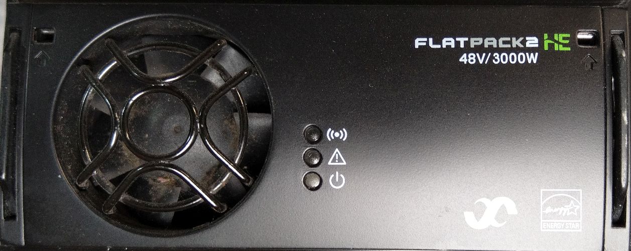
This is a PCB for monitoring / setting up the Eltek 48V 2kW and 3 kW Rectifier / PSUs which have been appearing surplus (ex telecom) at good prices. They communicate via a CANBUS interface and can be driven by an Arduino Nano or Nano Every, with a suitable interface, LCD and buttons. There are also connections for I2C and Serial should you wish to utilise them
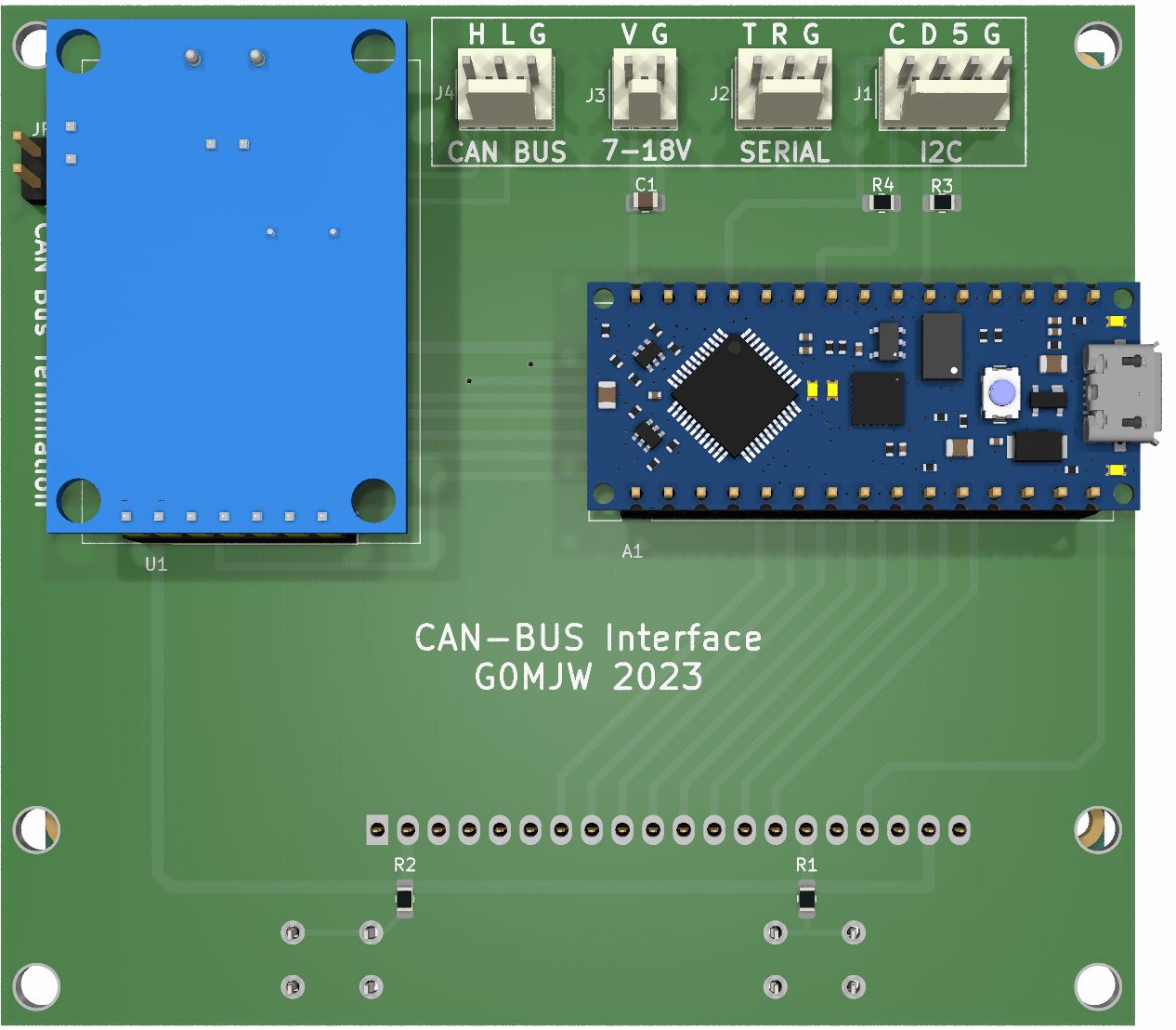
It is powered by 7-12V, it could be powered from the PSU with a suitable buck converter.
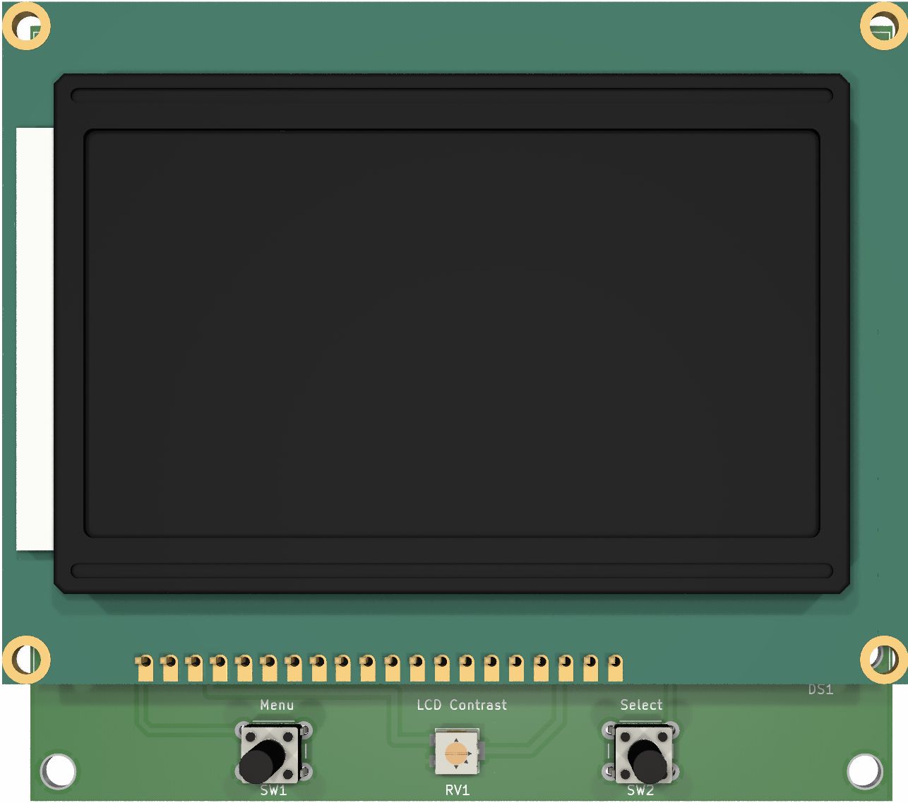
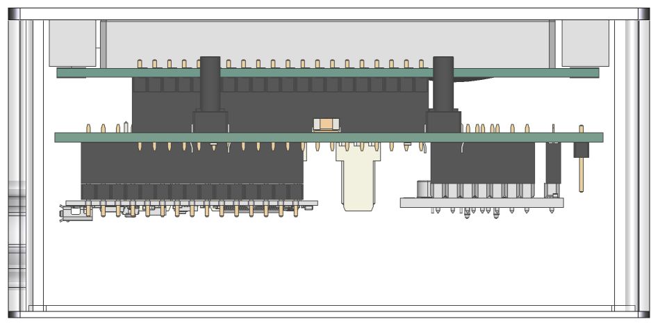
Here is a 3D Printed enclosure 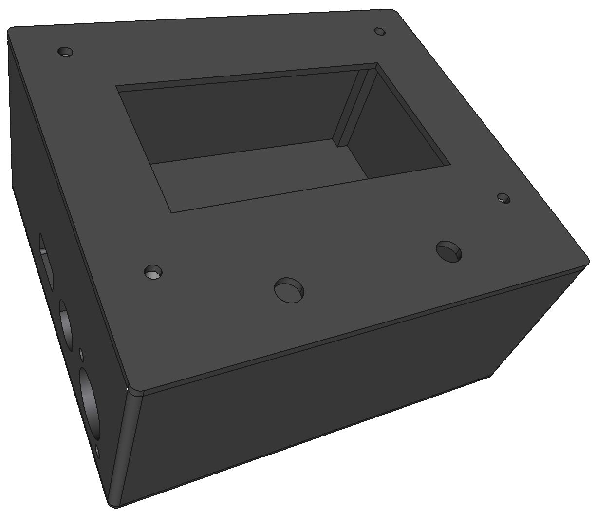
The case is designed assuming you are using a socket for the LCD, this makes it stand off from the main board by the height of the header, typically there will be 15mm between the top of the main board and top of the case. If you don't have a 3D printer you can always use a diecast box instead and mount the buttons off the board.
The connectors I used were a 5 pin 240 degree DIN socket for the CAN Bus signals and a standard panel mounting DC jack socket type DC-022 for the power.
My software is based on work by the6p4c which in turn uses this MCP_CAN library , both available on github. My development of this is a work in progress and initially it currently only monitors the PSU and will not adjust anything until I can make sure it doesn't do anything unwise. Software that utilises the buttons for setting up the PSU is in development. See the source code for details. If you just want to set the voltage, see the64pc's github for an example. Switching PSU for various applications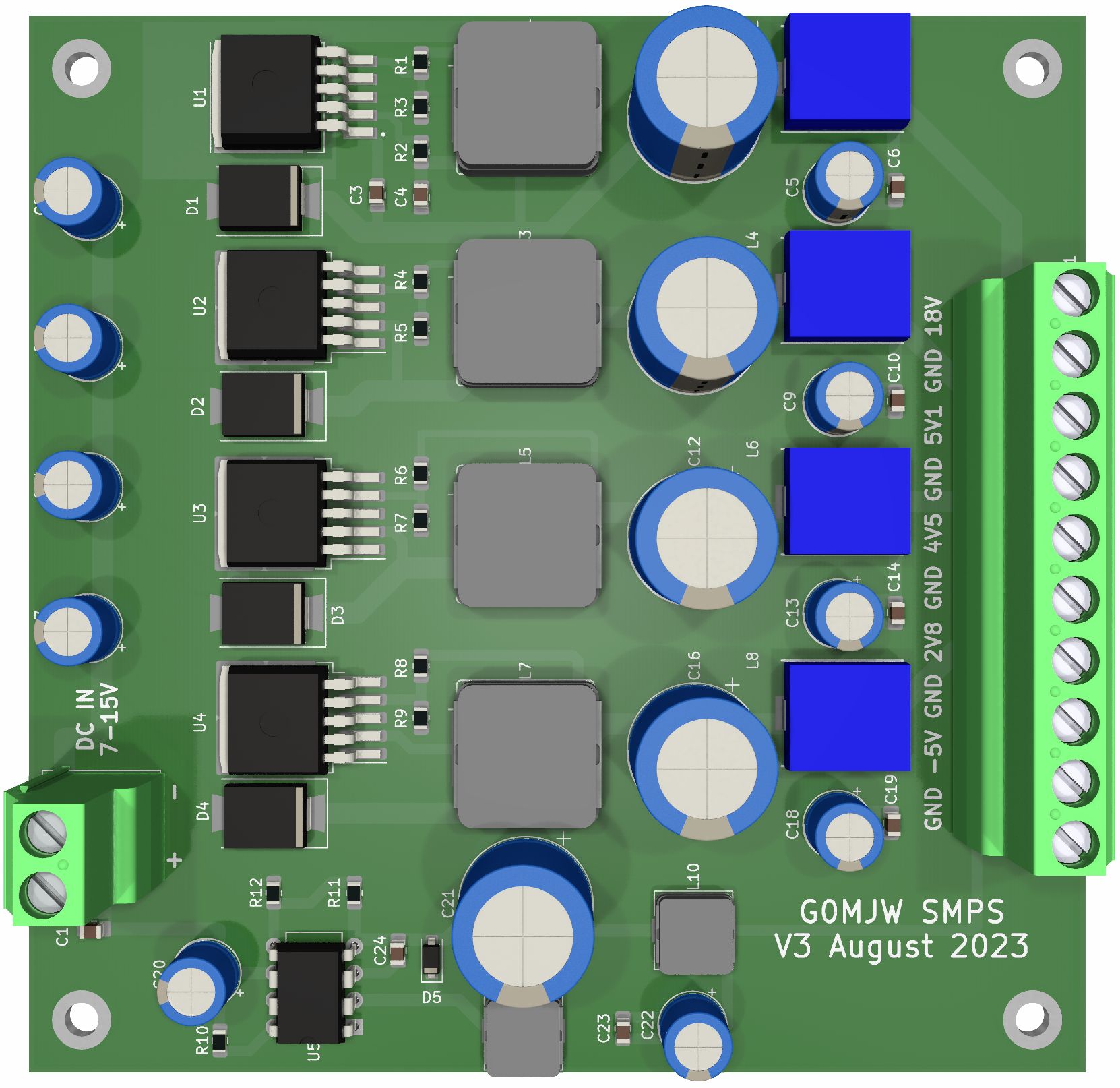
This is a PCB for generating various voltages at around 2-3A from a 12v supply. It uses the Simple Switcher Regulators, one Boost regulator to produce a higher voltage, e.g. for 24V relays, and four Buck regulators for three lower voltages and one negative rail. It isn't necessary to build them all.Good quality capacitors are essential. I am waiting for prototype PCBs to arrive to test this. For once, no software is needed.
Schematic Gerbers Bill of Materials IC9700 PTT Switching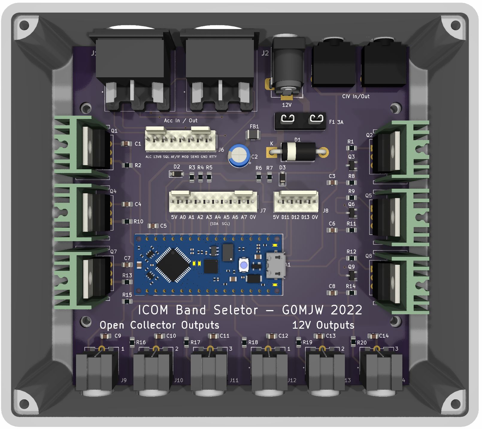
The IC9700 is a great radio but there is only one PTT output and not one per band. Why Icom did this is inexplicable as it makes controlling pre-amps and power amplifiers harder than it needs to be. I developed this board a while back to address this, after playing with the pre-amp voltage and ruling that out, as it only works with the pre-amp enabled, I was using an Arduino nano, based on an idea from ON6MH sniffing the C-IV band data to provide a simple PTT logic low for each band. Later on found I needed a +12V signal to control relays for each band and a more robust open collector PTT that could directly drive coaxial relays so I integrated all that into one PCB and designed a 3D case to go with it.
I'm aware this type of unit is available commercially from several sources and that's probably the best way to go for most people, but sometimes it is fun to make your own and develop software to do exactly what you need it to do. I am still working on the software - so far it only does simple band select for the primary band. The IC9700 is dual band and I'm not really sure how to deal with that as it really depends on what you are trying to do. Perhaps I will figure it out. Since developing the antenna switch, I have gained a lot more knowledge on how to read, write and use the C-IV data. For example, you might want to set different power limits depending on mode or apply some other logic depending on ADC levels, VSWR or whatever.
The spare IO pins are brought out to headers to facilitate expandability and although the board doesn't have a display, an I2C LCD or even just LEDs can be added via these headers, which also have 0V and 5V connections. Of course if you just want a PTT per band, there is no need for a display or 12V outputs.
I have written some basic software, but it needs much development. I have put it here to get you started. The rest of the project is ready, if you plan to develop your own code.
Rudimentary IC9700 Switch Arduino Software
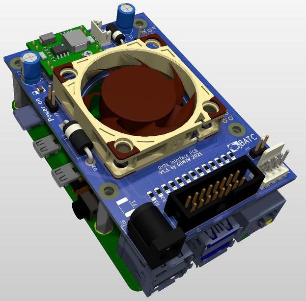
Ryde boardThis is a plug in board for building the BATC Ryde DATV receiver project with the minimum of wiring required. It provides the 5V PSU, a cooling option and Ryde IO interface. The information is all below. There are two PSU options, only one is required.
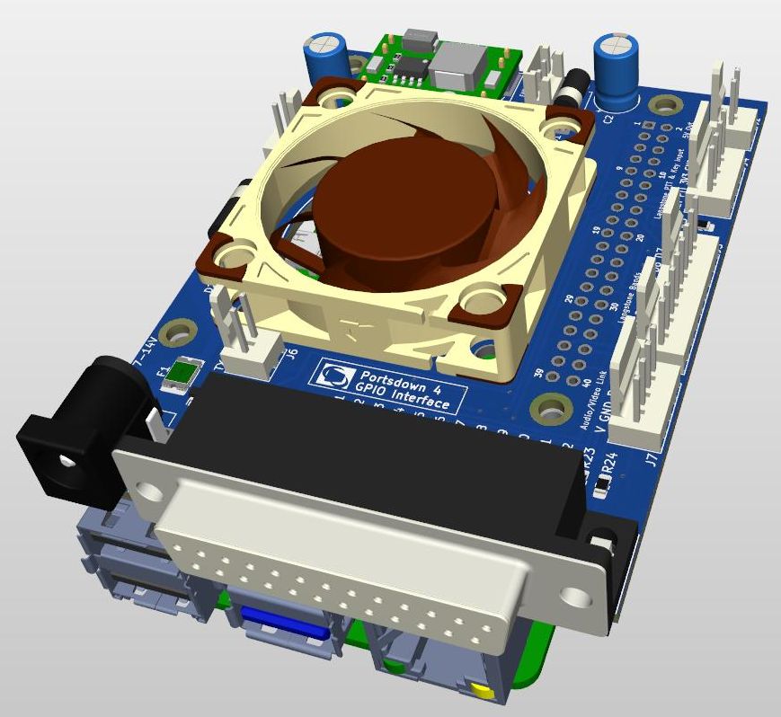
 Portsdown 4 / Langstone Interface board
This is a very similar PCB to the one above but is a bit larger and has the DB25 way connector used in the Portsdown 4 for interfacing to test equipment. It also has the fan, the headers for the Langstone and a PSU. The idea being to produce a neat, compact unit and minimise the amount of wiring needed. The audio needs to be connected from the PIs' 3.5mm jack to the header if you want it available on the DB25. Otherwise there is no need to bother with this. There is also a PTT driver transistor which is an open collector NPN able to sink about 100mA.
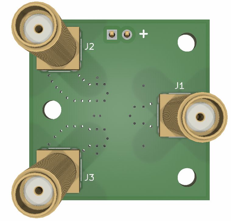
 RF Changeover Relay board
This little board is for mounting the very useful HF3 Series of High Frequency relay. A surface mount diode e.g 1N4148 type is needed to counter the relay back EMF. The board is designed for SMA connectors mounted on the back side and works well up to 70cm. It is OK at 23cm but not great at 13cm. These relays are not high power, 10W or so maximum.
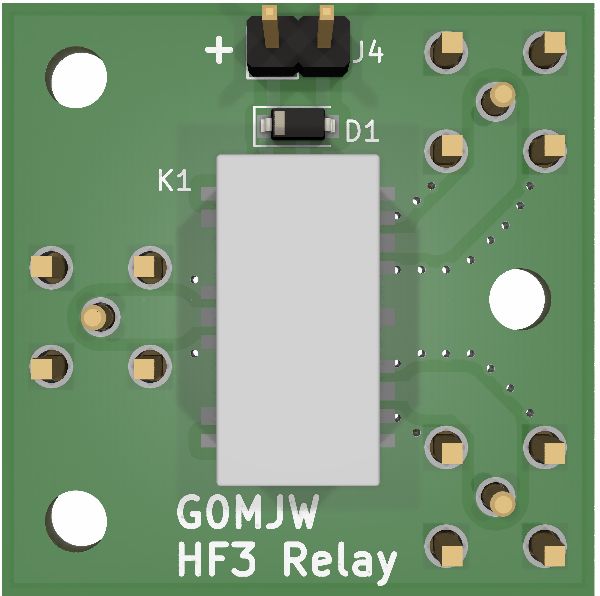
I have also made an edge mount version with a driver transistor
The information is here - all in one zip. There is no BOM, no need with so few parts. The resistor and capacitor are 0805 sized. The transistor and diode are the standard SOT-23 and SDO-123 packages respectively. The relay is your choice of voltage rating. The connectors are the ones intended for PCB edge mounting on 1.6mm FR4.
Coming Soon (maybe) Thinking what to do next. I have various controller for LDMOS power amplifiers but each specific to the application. There are also several projects in the BATC Wiki.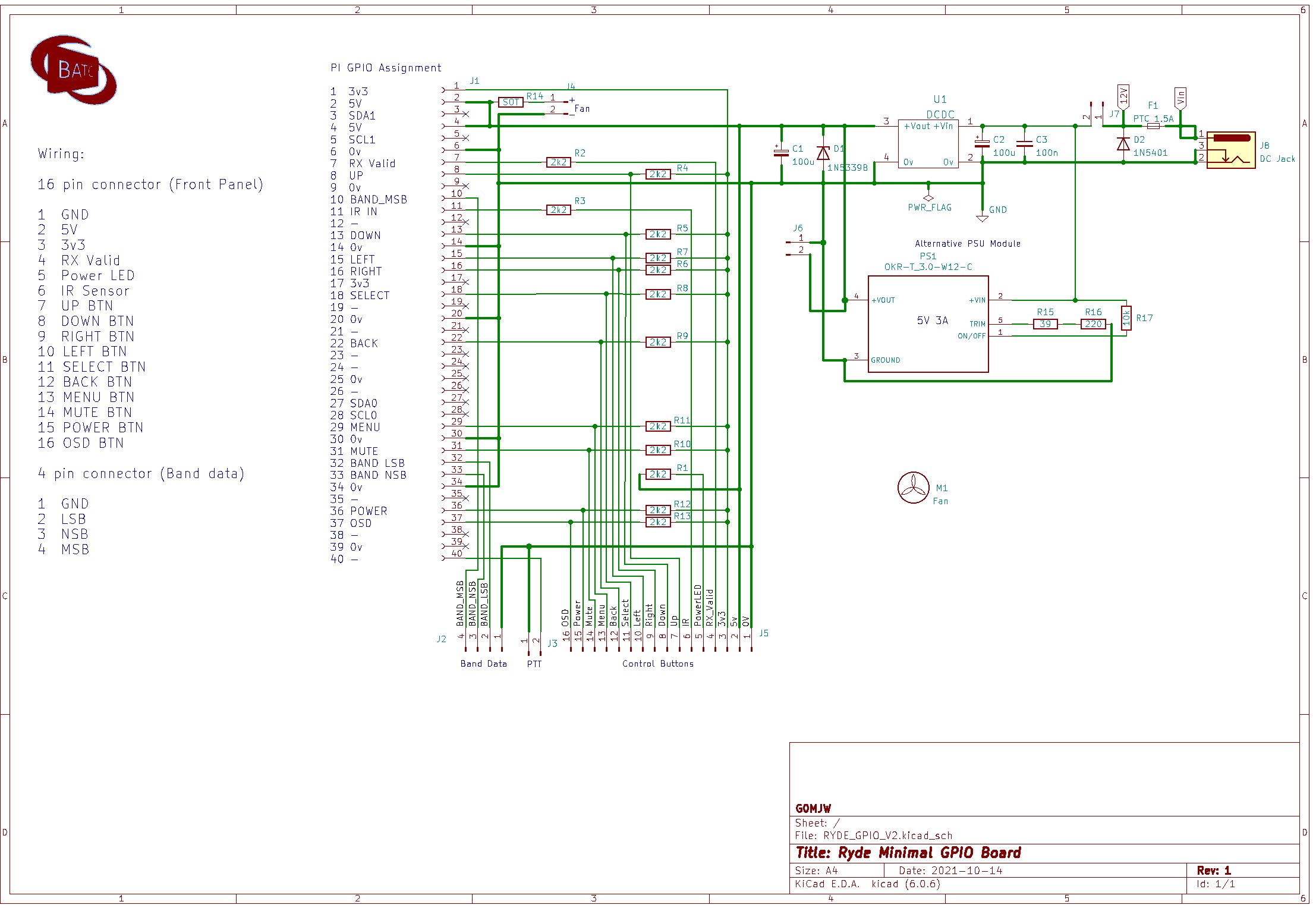