|
The G0MJW Pages |
![]()
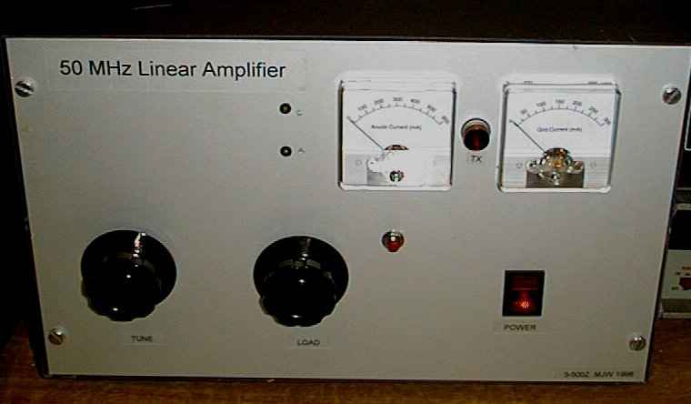
My 6m station consists of an all mode transceiver, usually the Elecraft K3, a my dualband 6m/4m beam and a home made 3-500Z linear amplifier, producing a clean 400W of RF, or a solid state 300W PA producing somewhat less clean signals. The background noise level is quite high here in IO91JO, as is the competition when the band is open. If I can hear it well, I can usually work it, but 400W is not enough for the larger pile ups from this site, especially as I can not put up large aerials.
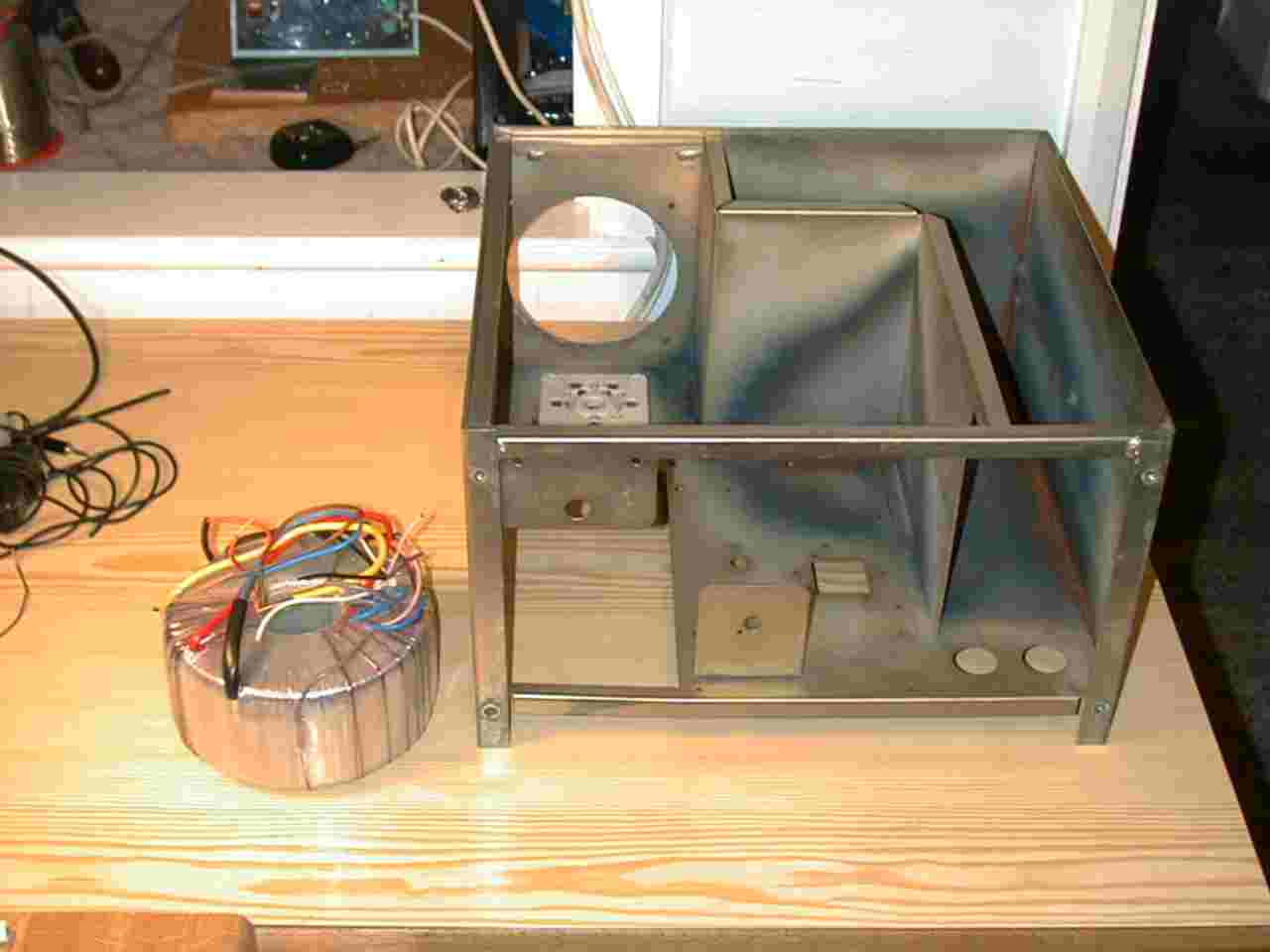
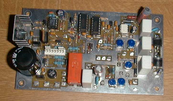
The 6m valve PA consists of a steel chassis containing all the bits. The PSU is made from a torroidal transformer, with two 500V windings in series, voltage doubled with a pair of HV diodes. The capacitor bank consists of 20 220uF, 385V 2.2 amp capacitors configured as two banks of 88uF 1.9kV, resulting in a 44uF, 3.8kV rating. The EHT is 2.8 kV off load, dropping to a worrying 2.35kV at 400mA. An extra winding on the transformer can be used to boost the EHT to around 2.8 kV on load, if required, which it isn't. The transformer also supplies the 5V filament supply and the 12V supply for the relays. A second transformer runs the control system. The control uses an early beta version of the GM3SEK triode PCB. As this is in the same case, beta testing showed that RF immunity could become a problem. This was fixed for the released PCBs and they work very well.
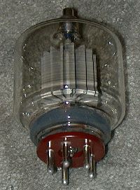
The RF circuit is a classic PI-L output stage. To improve efficiency, the minimum possible tuning capacitor was used, around 10pF, wide spaced. The tank coil is made from 6mm copper plumbing pipe and the loading capacitor is 150pF.The input circuit is a simple T-match. A 100mm axial fan cools the 3-500Z by blowing air across the side. This requires that the valve socket is offset below the chassis by 6mm to allow air to pass over the base. This cooling scheme is OK as I don't drive it hard to reach 400W of SSB/CW. I don't use it on RTTY, SSTV or FM !
Here are some images of the amplifier. I didn't have a digital camera when I started, so the collection of bits is not shown in much detail. Sorry.
 +
+ +EFFORT
=
+EFFORT
=
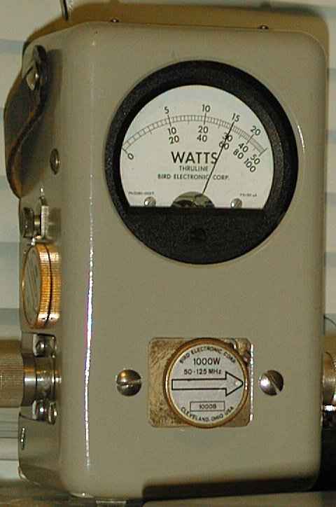
The maximum output has not been investigated, I don't want to blow up the PSU which is the limiting factor. The above image shows a test at 600W into the load. This required 60W of drive. Typically I run it with 40W drive for 400W output. The Anode current is 300-400mA and the grid current is 100-150mA. Efficiency is around 50% if you load it up properly in linear mode.