|
The G0MJW Pages |
![]()
I have been working on my 70cm station recently. The home set up consists of a multimode tranceiver (an Icom IC910X), a 180W amplifier (converted TV transmitter using a 4CX250K) and a 19 element vargada antenna with a mast head preamplifier. I am not in a favourable location for 432 MHz, but have managed to catch a few openings.
GS35B Amplifier and PSU.
One of my recent projects has been to produce a high power 432 MHz system. This is based on a GS35B amplifier from PA3CSG, and a home made PSU. I don't know the maximum output yet as my power meter only goes up to 1kW. 25W drive gives up to 750W output when the loading is set for that level. We have used this sucessfully in several contests, at the 400W level of course.
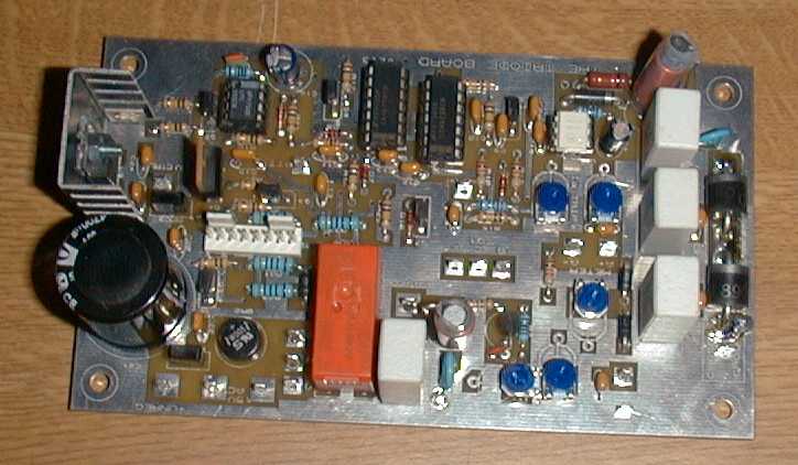
The PA was built by Geert, PA3CSG. I modified it a little to improve the mounting of the valve and put it in a case with changeover relays and a Triode control PCB from GM3SEK. I also built the PSU.
One of the hardest parts to obtain in this country is the EHT transformer. Fortunately, I have found a good custom supplier in Bradford in the UK. For £120, I obtained a 2kVA custom transformer producing 2.6 kV. The 2kVA rating is a compromise between output and weight. It will easily handle a large overload for SSB application. The PSU is a conventional four diode bridge, with microwave oven diodes. The capacitor is a 40uF oil filled (non-PCB) type from Fair Radio in the USA. I have heard these do not work well at ripple current. I connected it across the mains with a variac and ran 2A ripple for an hour. It didn't get warm. Lets hope it is OK. The EHT is switched by the control PCB in the amplifier itself. It can sit on the floor out of the way. I put an voltmeter on it so I know when it has discharged and I can see if the regulation is OK. Output is 3.3kV on load, 3.8 kV off load. This is a large drop, but quite a bit of it is caused by the mains volts dropping ! Yet more is caused by the 100 ohm safety resistor in series with the EHT. There are over current and under voltage trips built into the supply - with a meaty relay to disconnect the mains. There are also EHT fuses, as used in microwave ovens - in case of accidents.
Here are some pictures. Details on the amplifier can be found on Geerts' site.
 |
 |
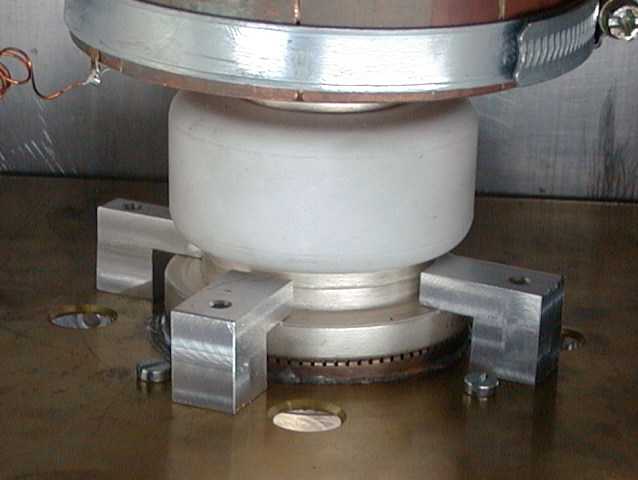 |
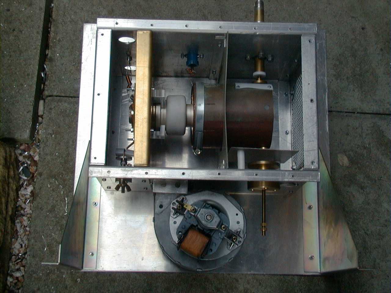
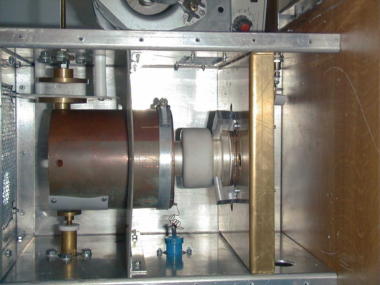
| The PA Section before fitting the relays and control circuitry.Note the anode loading is adjusted from the rear. It does not need adjustment once set up. | A close up of Anode cavity. The amplifier looks clean and simple to reproduce. The anode resonator is copper tube. Tuning and loading disks are evident. The PTFE is to prevent flashover in the loading capacitor. | A close up of the grid mounting. The courier demonstrated the requirement for this addition to Geerts design. The amplifier can now be mounted with the valve horizontal. |
 |
 |
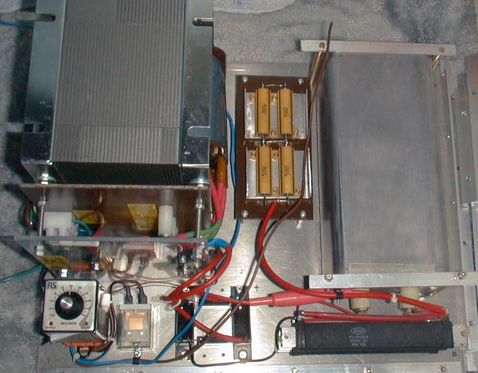 |
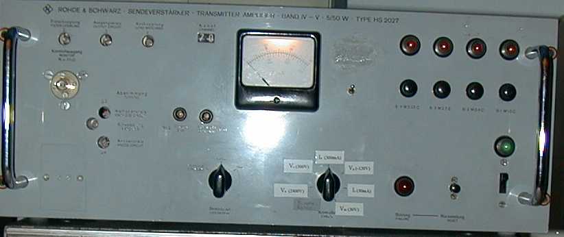
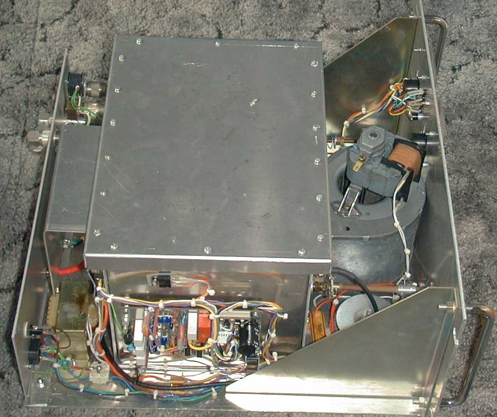
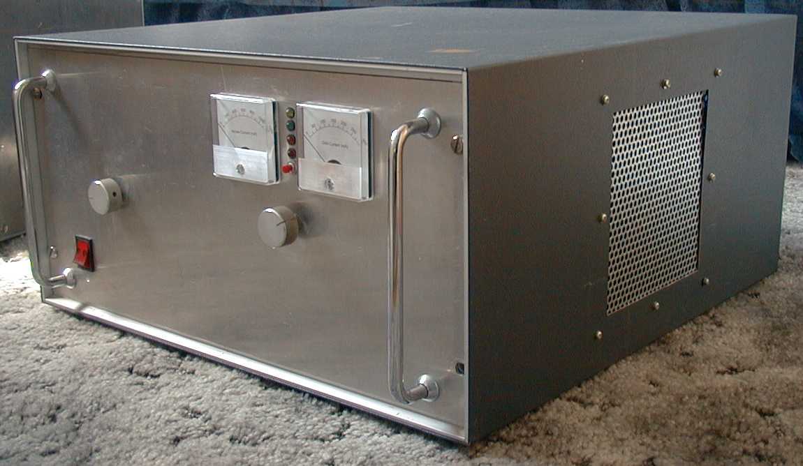
| The finished amplifier, outside its case. The control PCB is visible in the forground. I optimistically use a CX520D relay. PTFE coax is required at these power levels. | The PA cased and ready to go. The meters show anode and grid current. The LEDs are control and fault indicators. The two controls are grid tune and anode tune. | PSU under construction. The time delay relay and anti surge resistors can be seen below the transformer. The large resistors bottom right are the EHT bleeders. The four gold resistors are the EHT series safety resistor.. |
 |
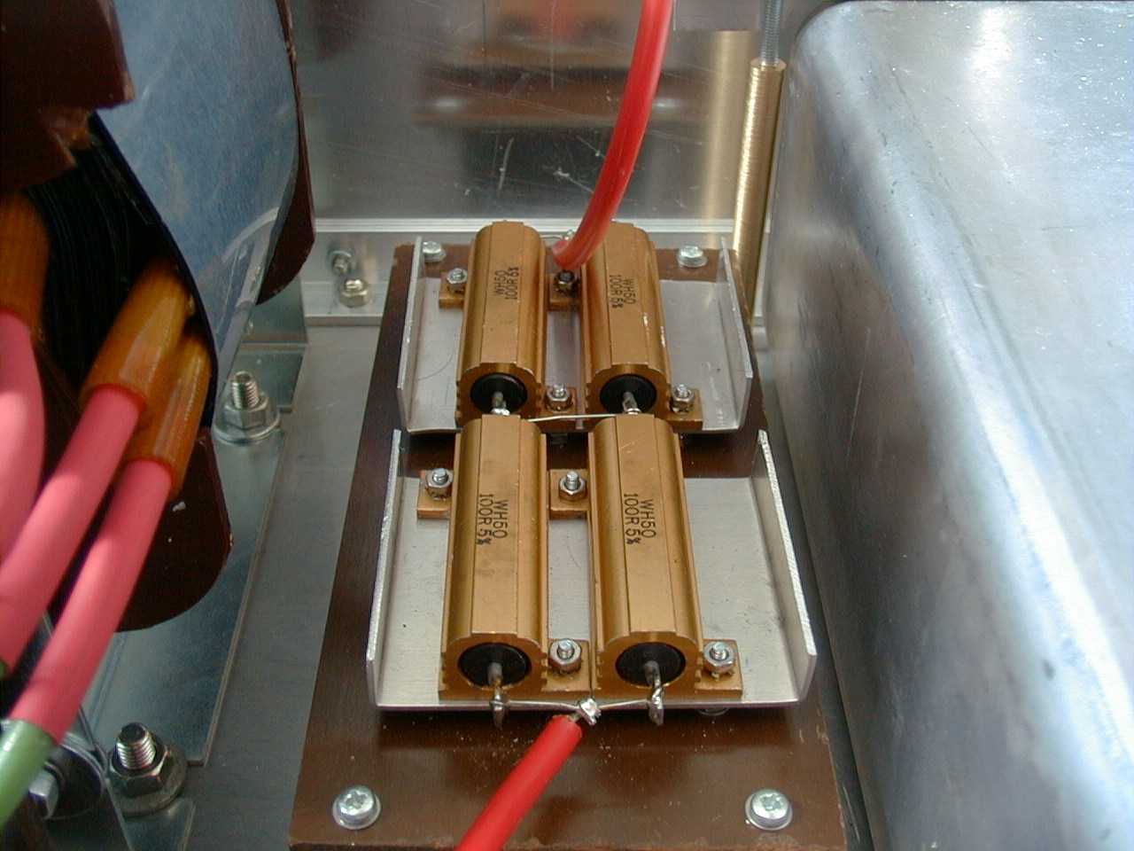 |
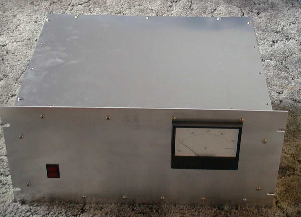 |
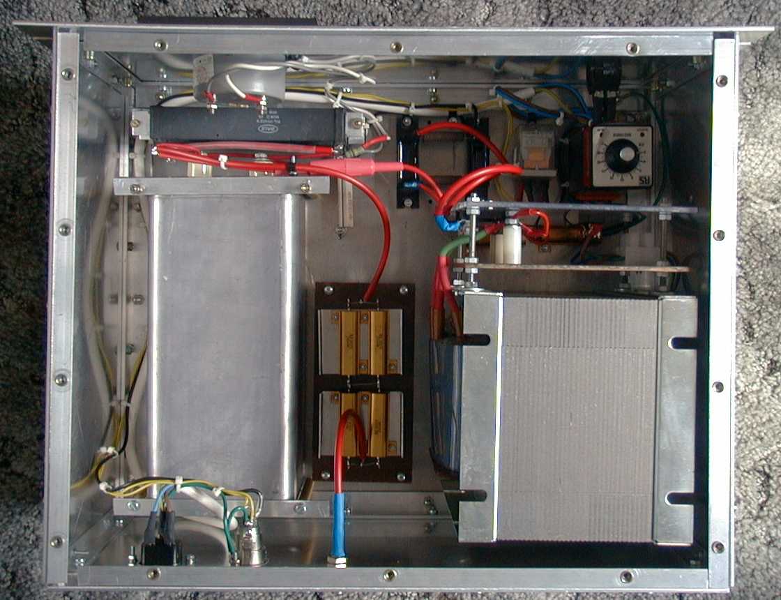
| A finished PSU - with the lid removed. The total weight is just under 40 kg. Heavy, but managable. | Close up of the safety resistors. Note the extra insulation. Even so, the rating is marginal. These resistors will not survive an extended shorted output. They ought to last longer than the fuse. | The completed PSU. The meter reads the EHT. The power switch is used to isolate the supply, it is commanded on by a control signal from the amplifier. |
Test Data:
| Output | Drive | EHT | Anode Current | Anode Dissipation |
| 600W | 25 W | 3.4 kV | 450 mA | 900 W |
| 800W | 35 W | 3,3 kV | 600 mA | 1150 W |
| 1100W | 50 W | 3.3 kV | 800 mA | 1400 W |
The amplifier was loaded correctly at the maximum output, so efficiency could be improved at lower levels. The efficiency could also be improved by loading more lightly paying careful attention to the grid current. Reports of similar amplifiers run at 3.8 kV and above have indicated over 2 kW output.
The 1100W level was end stop on the Bird 43 with a 1000C slug, plus 3 bounces of the needle.