|
The G0MJW Pages |
![]()
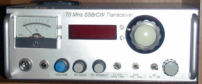
I like 4 metres. The UK band is 70-70.5 MHz. There is not much commercial equipment made for this band as so few countries have it. For this band I use a transverter from 28 MHz. I also built a 70 MHz CW/SSB transceiver, which works well, but does not have the facilities of my HF transceiver.
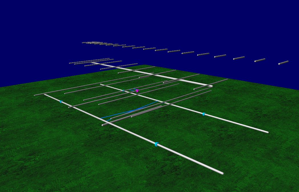
My aerial for the band has to share its location with aerials for 10m, 23cm and above. It is a home made 4 element yagi interlaced with a 3 element 6m yagi. This is a design by the late W4RNL. I have tried several other designs, including the 6m-4m log periodic published in Radcom many years ago, but they did not work as well. Here is the simulated pattern using 4nec2.
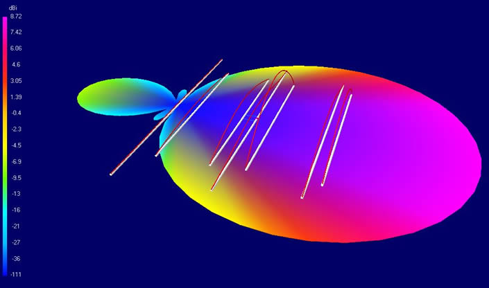
I also simulated it with all the other nearby antennas and ground and noted it loses about a dB or so from the proximity of the other antennas and the front to back was not so good, but it gains via ground reflection. This is pretty much as expected and a not so good antenna is better than no antenna at all.
The radio is a converted Elecraft XV50 transverter, now operating on 4m which I drive with my Elecraft K3 transceiver. This combination works very well and is able to drive the several linears I have built over the years.
Unfortunately, 4m is one of the noisiest bands at my location. This was evident on a trip to Cornwall for the 1999 Eclipse that coincided with the 4m trophy. Our site was remote and quiet, I had to check the receiver was OK as there was so much less noise. It is a pity only 30 stations bothered to beam Southwest - or maybe they have the same problem I do at home. If you call and I don't hear you, remember I have a sensitive receiver, but it can not get round the band noise.
Mk1.
Although my transverter is capable of producing 10W, this is not really enough, so I have built several amplifiers for the band. My first used a QQV06-40 dual tetrode and produced about 50W. A converted Belcom 2m amplifier was found cheaply at a rally in a non-working state. The PSU transformer was fine, but some components had burnt out. The two parts of this dual-tetrode were operated in push pull. I initially had some problems with instability that I fixed by using a torroidal transformer style grid circuit. This amplifier was also re-tuned to 6m where it produced 110W in class C in a short test.
Mk2.
I bought an old NAG144XL 2m linear amplifier at yet another rally. This was a fully working linear. In its original state, it employed a single 4CX350F in grounded grid configuration. This produced 250W on 144 MHz, plus quite a bit of third harmonic on 70cms and spurii all over the spectrum. It could not do it for long though as the cooling was woefully inadequate. The original 4CX350F had probably died from overheating as it had been replaced with a 4CX350A at some time. A transformer for the 6.3V heater supply required by the 4CX350A had been bolted to the top of the cabinet.
Not needing another 144MHz amplifier, I decided to convert this NAG to 70 MHz. I first modified the anode circuit, removing most of it and replacing the tune and load capacitors with larger value Jackson ceramic types. The new circuit is a PI-L design, using some copper pipe for the coils, 3 1/2 turns 3mm gas pipe on 20mm diameter for the tank and 4 turns of 1mm wire of 10mm diameter for the L. The input circuit was modified to grounded cathode, grid driven with a L match and a 50pF tuning capacitor. I also replaced the valve base for an SK610 as some of the finger stock on the original was damaged.
The screen supply was shunt stabilised to improve the linearity. The original screen supply was not regulated at all! The SO239 RF connectors were replaced by N-types. The rest of the amplifier was left as originally supplied.
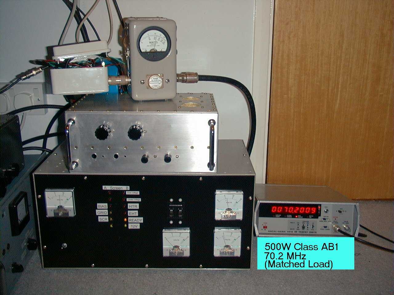
This amplifier works well, producing over 180W of output with good linearity. I have seen 250W into a dummy load but at this level the valve was almost at saturation and I doubt all the extra power was in band. As the UK legal limit is around 170W - the performance is adequate. The cooling system is still insufficient for extended high power use, but for occasional SSB, it is OK.
Mk3
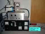
The NAG amplifier worked well enough, but there was a rumour the 4m limit was going to be increased to 400W. I had found a dual 4CX250B PSU at a rally that could be made to work and I had a K2RIW 2x4CX250B chassis from GHP that I had consistently failed to make work on 70cms. I had by this time given up on the K2 and built a GS35B for 70cms, so I used the chassis for my MK3 4m amplifier, a pair of 4CX250Rs. Some pictures of the amplifier are below, click on the images for an enlarged version.
 |
 |
|
 |
 |
|
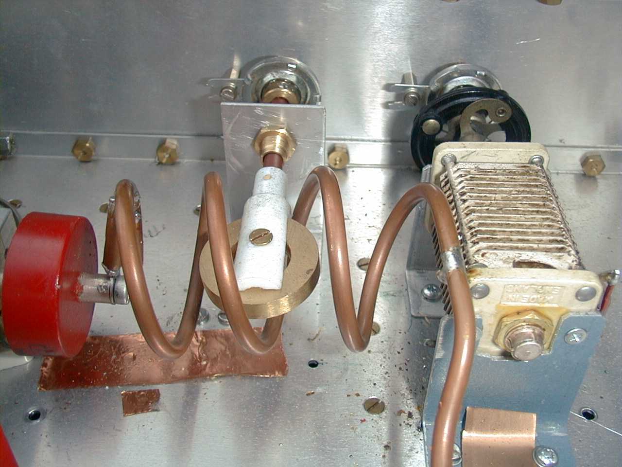
Ia = 500mA, Is=-5mA, Ig=0, Va=2kV. |
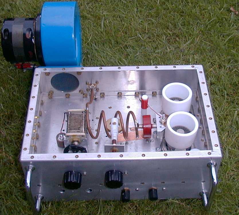
Note the size of the blower & K2RIW cooling method. |
The brass disk is the tune control. It is held in a chunk of PTFE. |
Another close up Capacitance
around the anodes has been minimised.
|
This uses the GW4FRX/G4FRE design shown in the "VHF DX Book". |
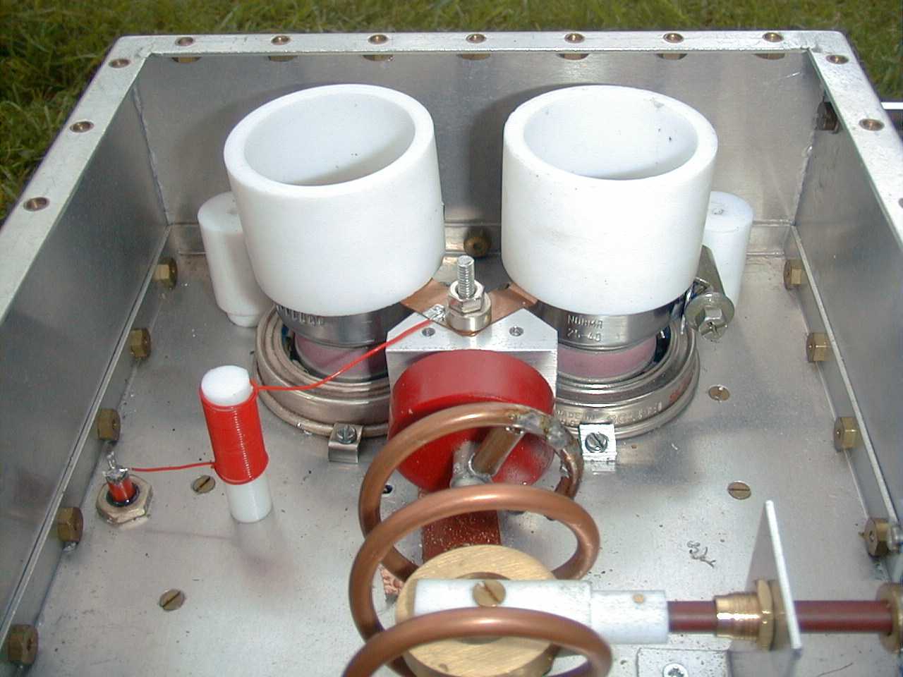
The pair of 4CX250s came from Russia, and are operated in parallel. At this frequency, one can use either VHF techniques such as tuned lines or conventional coils as at HF. A 1/4 wave line is uncomfortably long at 70 MHz so I stuck with a tank coil as usually used on HF/6m. Unfortunately, this high Q design requires close attention to detail to minimise tank coil losses, but can give excellent results in a small enclosure.
The circuit is a PI-L to help reduce harmonics but it does not look like it as the "anode tuning capacitor" consists entirely of the valve output capacitance and circuit strays. Those strays have been minimised. The reason for doing this, rather than a conventional tune capacitor, is to minimise the loaded Q to control tank circuit loss.
With no tuning capacitor, tuning has to be done by altering the inductance of the tank coil. I do this with a single shorted turn, made from a large brass disc, rotated inside the tank coil. It works well for the limited range required on the narrow 4m band.
The tank coil is made from 6mm diameter copper gas pipe, obtained from a caravan suppliers. The loading capacitor is around 100pF made up from a fixed and a variable. The variable is a split type so no RF current goes through the spindle. I doubt this matters at this power level.
The grid tuned circuit is a PI circuit using two 50pF Jackson variables a small coil and the appropriate grid bias blocking capacitors. The grids are swamped by several 2W 1K resistors, isolated by 100pF semco mica capacitors to aid stability. This technique works well, it reduces the gain and the extra drive is dissipated in the resistors. Without any resistors, the amplifier has high enough gain to be unstable through stray coupling between the input and output circuits.
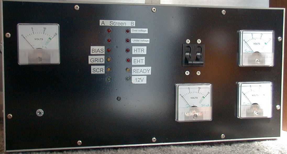
The PSU produces 2kV on load and is fully protected. Proper screen and grid regulators are used. Into the load, this amplifier produces an adequate amount of RF (700W) at up to 60% efficiency. On air, through a high power attenuator to reduce the level, I have received good reports of a clean signal from trusted local observers.
Tuning up is simple, tune the input for best match to the driver then tune the output controls for maximum output at low input power, reduce the drive to ensure less than 100W out. Readjust the input tuning if necessary and then gradually increase drive power setting the loading control for around zero screen current, or slightly negative screen current and peaking the tune control.
Do all this in short bursts to make sure nothing overheats. Tune for maximum efficiency at the chosen maximum power level while keeping the screen current negative. Never operate positive screen current and there should never be any significant grid current except in class C, if there is grid current on SSB the amplifier is being overdriven. Tune up only needs to be done once, the settings hardly change over the range of 70-70.3 MHz.
Mk4
All this messing around with valves is all very well but with short ES openings it is sometimes nice to have something that comes on instantly, does not make too much noise in standby and can be carried without aid. The MK4 amplifier uses an MRF151G RF power FET. The circuit is the one from the Motorola AR305 application note and was sold as a kit by Communications Concepts Inc.
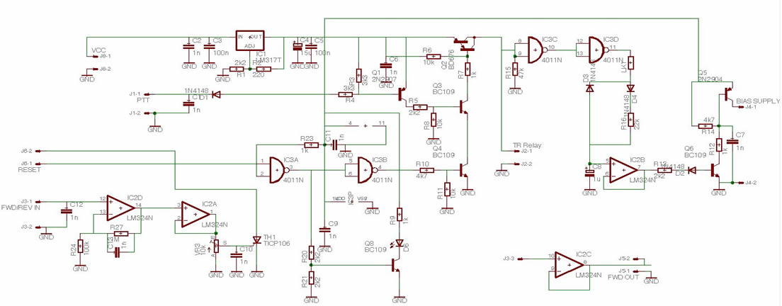
The MRF151G operates from a 50V supply and is easily capable of 250W SSB from 10 MHz up to 144 MHz. I built the PA module into a case with a 48V switched mode PSU, cooling fans, relays and protection against bad VSWR etc. The protection circuit is based on an SCR and is shown below. A PCB was made using Eagle Designer which is a very useful program with a student version that is free for personal use.
© G0MJW
Last Modified August, 2008