This section deals with atmospheric refraction or ray bending - why signals propagate beyond the horizon
The Detailed propagation course
HTML Propagation Fundamentals - Fixed Link Propagation - Mobile Propagation
PDF Fixed Links Propagation - Mobile propagation
Short and simple (the old tutorial)
Propagation in Free Space - Absorption by Atmospheric Gases - Diffraction over Terrain - Refraction and Ducting - Reflections - Troposcatter - Rainscatter - Sporadic E
Refraction on the troposphere relies on the variations in space of the refractive index n. Typically, the refractive index falls with increasing height. The refractive index governs the speed of propagation in a medium - which can be seen from the equation for the electric field in space and time:
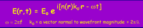
Equation 1
The value of n(r) represents the refractive index at the point r(x,y,z). If the refractive index falls with height, the wavefront will be progressively refracted downwards:
Figure 1
This downwards bending can compensate to more or lesser effect for the curvature of the earth - i.e. the radiowaves can propagate beyond the visible horizon.
Figure 2 - Propagation over horizon
Typically, the refractive index in the troposphere falls slowly with height and the resulting refraction causes the radio horizon to appear to be 1.33 times further away than the geometric horizon.
The value of the refractive index of air is very close to unity, typically 1.0003. To make figures easy a new value is defined - the refractivity:
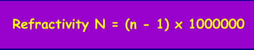
Equation 2
at sea level in the UK, N ~ 310 'N units'.
The refractive index of air and hence N depends mainly on the atmospheric pressure P(millibars), the temperature T(Kelvin) and the partial pressure of water vapour e (millibars) through the following relation:
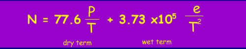
Equation 3
There are two terms, the 'dry term' which covering dry gases, mainly Nitrogen and Oxygen and the 'wet term' governed by water vapour. The atmospheric pressure falls exponentially with height, falling to 1/e (that is e an in natural logs) of the surface value at a height of 8km. Temperature falls by about 1 degree every 100m. The behavior of water vapour is much more complex as it is governed by the weather and is limited to the saturated vapour pressure (how much water the air can hold before it condenses as rain or ice). The saturated water vapour pressure is around 40 mbar at 300K (a warm day) and 6mbar at 273K (freezing). As a result, the amount of water vapour above the zero degree isotherm is negligible.
The net result is that N usually decreases by ~40 N units per km in temperate regions. This decrease is called the lapse rate of N. Variations in pressure, temperature and humidity do cause significant deviations in the lapse rate. Values of N that are less than -40/km cause sub-refraction and greater than -40/km cause super-refraction.
If the decrease of N with height exceeds ~157 units per km, the radiowaves will follow the curvature of the earth in a phenomenon often termed 'ducting'.
Figure 3 - Refractivity Profile of N vs Height [1]
Another parameter that is useful in studying propagation is the concept of the effective earth radius 'k' factor. Remember that radiowaves normally propagate 1.33 times the geometrical horizon distance.
For terrestrial planning, we are interested in the relative curvature of the radiowave compared with that of the earth. By using the concept of the k-factor, calculations of the distance to the horizon can be made more easily. It is possible to model propagation over the earth by appropriately adjusting the k-factor so that the radio waves appear to travel as straight lines and the earth 'bulges' less than usual. It is then easy to check for obstructions against a path profile. When the amount of adjustment to the curvature of the radiowave paths is by the effective earth radius, the radiowaves will travel in straight lines relative to the terrain. This is best explained by a diagram:
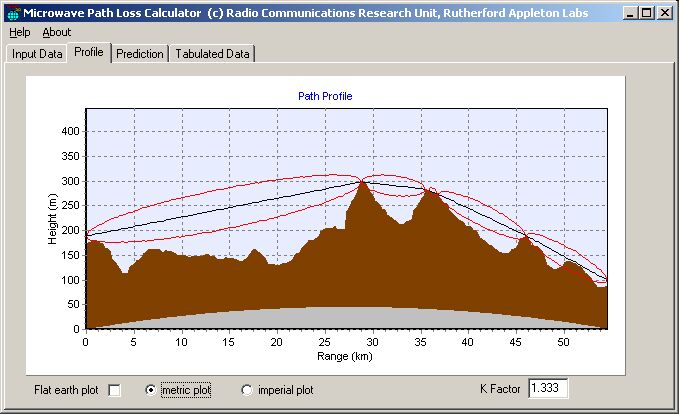
Figure 4 - A Path Profile
In figure 4, it can be seen that the terrain has been plotted with a correction for the "earth bulge" using a k-factor of 1.333. The radio path is plotted as a straight line on this plot. The red lines represent the first Fresnel zone - if obstructions come into this zone, the path is considered to be obstructed. It can be seen from the figure that this path has several obstructions that entirely block the path. At these points, the signal may still propagate, via diffraction and energy may propagate above these points by tropospheric scatter. In both these cases the signal is likely to be strongly attenuated.
Figure 5 shows a longer path - it is obvious that the earth curvature dominates the terrain over a long path and that very few long paths can be "line of sight" without very tall masts or mountains.
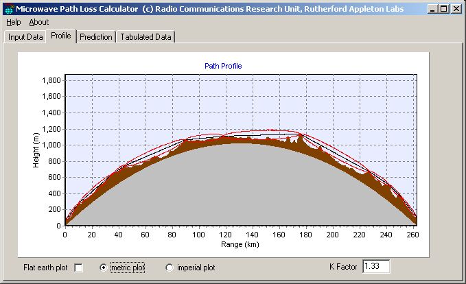
Figure 5 - Earth curvature dominates over terrain variations
Figure 6 below shows the same path, but this time with the earth bulge flattened out and the radio paths curvature compensated to account for this - it illustrates how hard it is to tell if a path is line of sight without using the effective earth radius concept.
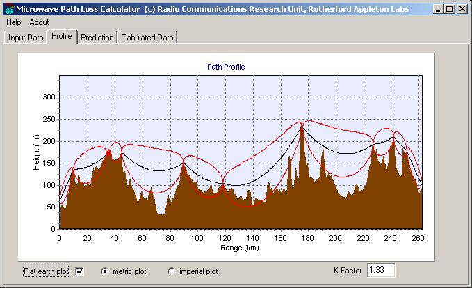
Figure 6 - Pretending the Earth is Flat
As has already been stated, the refractive index of the atmosphere generally falls with height with a lapse rate of -40 units/km and this leads to some bending of radiowaves towards the ground allowing them to propagate beyond the geometric horizon. This is normal propagation. When there is anomalous propagation the cause is of course an abnormal change in refractive index with height as shown in Figure 3 above. The anomalous propagation effects that are of most interest are those that cause radiowaves to propagate much further than normal.
It can be shown using the small angles approximation (sinq~tanq~q) that the radius of curvature of a radiowave is very close to the rate of change of the refractive index n with height.

Equation 4
The curvature of the earth is the inverse of the radius of 1/6378 km-1. This equals 157 x 10-6 km-1. Remember that the value of N is equal to n x 106 . Therefore if the lapse rate of N (dN/dh) is equal to 157 units/km the radiowave will follow the curvature of the earth. If the lapse rate is greater than 157 units/km radiowaves are bent down towards the earth becoming trapped near the surface and can propagate over very long distances.
The radiowaves can become trapped between a layer in the troposphere and the surface or even between layers in the troposphere depending on the refractivity profile. This is generally called a duct and is a waveguide like mode of propagation. As a result, energy is constrained into two dimensions as it can spread out horizontally but not vertically. This means the path loss increases directly with range rather than with range squared, resulting in much lower path losses and very high signal levels at long ranges.
When trapped between an elevated layer and the surface in a surface duct, extended propagation will occur if the reflection from the ground is low loss. The angles are small and low loss reflections can occur, especially where the roughness of the terrain is small compared to the wavelength. When trapped between layers within the troposphere in an elevated duct is formed and the refraction loss depends on the roughness of the layers.
Figure 7 - Surface and Elevated Ducts
(Note the radiowaves are really refracted by the atmosphere but that is very difficult to draw!)
For locations in Northern Europe, surface ducts occur for around 5% of the time and elevated ducts for up to 10%.
Frequency Sensitivity
There are two constraints on the ability of a duct to contain and propagate RF energy at different frequencies. The first, which places a lower bound on the frequency is that the size of the duct has to be sufficient to propagate in a waveguide mode. The second is that the roughness of the boundary layer must be low in relation to the wavelength as otherwise, energy will leak out of the duct. This puts an upper frequency bound on the ducts ability to propagate radiowaves. Small variations in horizontal refractive index generated through turbulence become increasingly important at microwave frequencies.
Surface ducts lower bound always follows the ground contour and the same is true to a lesser extent for the elevated boundary - radiowaves in ducts do not cross mountains.
Coupling into a duct
Ducts can only trap energy if the angle of incidence at the duct is relatively small - a value derived from Geometric Optics [1] gives the maximum angle in comparison to the refractivity gradient:
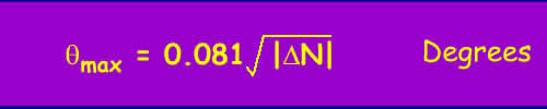
Equation 5
As the refractivity gradient across the layer is unlikely to be more than 50-100 N units, the maximum coupling angle is under a degree and very often much less. That means that effectively to couple into a duct well, the elevation to the horizon should not be greater than 0.5 degrees and conversely that a fair amount of protection from long distance interference can be obtained using site shielding.
The major cause of ducting is humidity and temperature inversion. The pressure lapse rate does not vary much as winds soon restore equilibrium. Differentiating equation 3 and substituting typical starting values of Pressure P of 1000mbar, Temperature T 273k and water vapour pressure e of 15mbar gives a sensitivity analysis in equation 5.
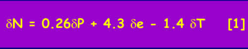
Equation 6
Ignoring the pressure we will concentrate variations in the lapse rate of N promulgated through variations in e and T.
Evaporation Ducts
There is usually a region for a few metres above the surface of the sea where the water vapour pressure is high due to evaporation. This also occurs over large bodies of water, for example the great lakes. The thickness of the duct varies with temperature of the location, typically 5m in the North sea, 10-15m in the Mediterranean and often much more over warm seas as in the Caribbean and Gulf. Naturally, these ducts have a significant effect on Shipping and have been extensively researched. It is the reason that VHF/UHF propagation over sea can extend to great distances causing all sorts of international frequency co-ordination problems.
Temperature Inversions
Usually, temperature falls with height by about 1K per 100m. On clear nights the ground cools quickly and this can result in a temperature inversion, where the air temperature rises with height. If it is dry, the temperature term is dominant in Equation 5 and super refraction and ducting can occur. This is particularly common in desert regions.
If there is significant water vapour the relative humidity can quickly rise to 100% and vapour condenses out as fog. This condensation reduces the water vapour density near the ground leading to cold dry air near the ground, warmer moister air above and results in sub-refraction. This can lead to multipath on otherwise apparently perfectly good line of sight links.
Subsidence
This is a mechanism that can lead to elevated ducts and is associated with high pressure weather systems - anticyclones. Descending cold air forced downwards by the anticyclone heats up as it is compressed and becomes warmer than the air nearer the ground leading to an elevated temperature inversion. (Atmospheric pressure always increases closer to the ground). This all happens around 1-2km above the ground far too high to cause ducting except for very highly elevated stations as the coupling angle into the duct is too great for a ground based station. As the anticyclone evolves the air at the edges subsides and this brings the inversion layer closer to the ground. A similar descending effect happens at night. In general, the inversion layer is lowest close to the edge of the anticyclone and highest in the middle. Anticyclones and subsequent inversions often exist over large continents for long periods.
Advection
This is the movement of air masses, typically occurring in Early evenings in the summer with air from a warm land surface advecting over the cooler sea. This warm air mixes with the cooler air which is relatively moist through being close to the surface of the sea. This leads extending the height of the evaporation duct and to high humidity gradients and a temperature inversion forming a surface duct within the first few 100m above the sea. These ducts do not persist over land and are a coastal effect. Typically in the UK they are associated with warm anticyclonic weather over the continent of Europe and advection out over the north sea. They tend to be weaker than subsidence ducts but do occur relatively often over the North Sea and can persist for many days. For example, it is relatively common for UHF signals to propagate well beyond line of sight from the East coast of England across the North Sea to the low countries.
[1] Propagation of Radio Waves - Editors M.P.M Hall, L.W. Barclay, M.T. Hewitt, Published by IEE 1996 ISBN 0 85296 819 1
© Mike Willis December 26th, 2006