

This section deals with the attenuation of radiowaves by atmospheric gases
The Detailed propagation course
HTML Propagation Fundamentals - Fixed Link Propagation - Mobile Propagation
PDF Fixed Links Propagation - Mobile propagation
Short and simple (the old tutorial)
Propagation in Free Space - Absorption by Atmospheric Gases - Diffraction over Terrain - Refraction and Ducting - Reflections - Troposcatter - Rainscatter - Sporadic E
As radiowaves pass through the troposphere they undergo interactions with the gas molecules that are present in the atmosphere. The composition of the atmosphere at sea level is:
Each of these gas molecules interacts with the radiowave, the interactions may or may not cause loss of energy and hence attenuation. Losses are especially high near the resonances of the molecules. E.g. when an asymmetric molecule (e.g. H2O) is placed in an electric field, it will try to align itself to minimum potential with respect to the electric field:
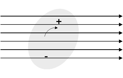
Polarised molecule in Electric Field
This process causes loss. The complex permitivity of the gas shows a resonance - the imaginary part is the absorption. The resonance frequency varies with temperature.
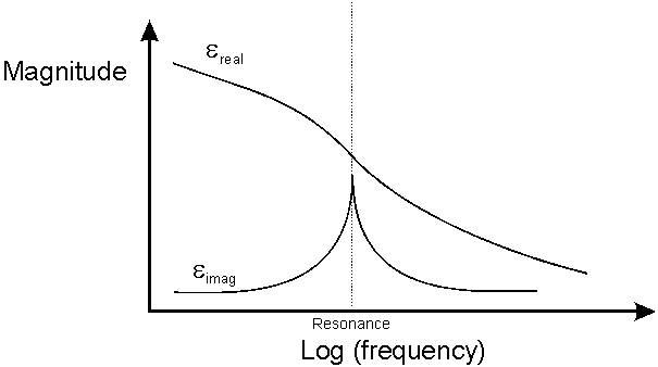
Complex Permitivity of a Gas
Other resonance mechanisms also occur and are really beyond the scope of this tutorial, but the important thing to remember are that the absorption depends mainly on:
The atmospheric pressure is also important. The resonance modes of the molecules are discrete, but as the molecules are constantly in collision with each other and moving at random, the resonance lines become broadened. Below about 10GHz, Gaseous attenuation can be ignored for most purposes. In the amateur radio bands, at 24GHz and 47GHz expect between 0.1 and 0.2 dB/km, which does start to build up on 100km+ paths.
The important resonances for gaseous absorption up to ~300GHz are those from atmospheric Oxygen and Water Vapour. The quantities and effects of resonant gases (CO, NO , NO2, N20, SO2, O3) are negligible compared to water vapour at typical microave link frequencies.
Oxygen has strong bands of resonances around 57-60GHz and 119GHz. At sea level, the losses can amount to15 decibels per km at between 57GHz and 63GHz.
Water vapour has a resonances at 22GHz. 183GHz and 324GHz. The attenuation changes with the amount of water vapour in the atmosphere. A typical figure for the water vapour density at sea level in Europe is 7.5g per cubic metre.
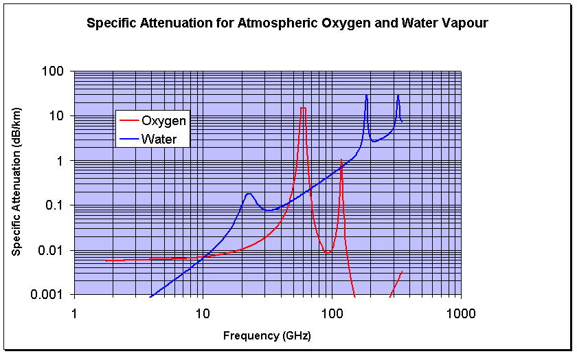
Calculating Atmospheric Attenuation
A really good model for atmospheric gas attenuation is available from the ITU-R in ITU-R P.676-6 "Attenuation by Atmospheric Gases". I have a software implementation of this on my software page A rough and ready rule of thumb type model, that gives reasonable results away from the resonance lines is given below:
Rough Model for Sea Level Gaseous Attenuation
This model is simply a curve fit - as such it can not be expected to give highly accurate results, but it can give a good idea of what to expect.
The attenuation due to water vapour is:
Awater = 
Where p is the water vapour concentration in grammes per cubic metre and f is the frequency in GHz.
The attenuation due to Oxygen is:
For frequencies less than 57GHz:
AO2 =

dB/km
For frequencies >63 GHz:
AO2 =
 dB/km
dB/km
Between 57 GHz and 63 GHz the model does not apply - An average value of 14.9 dB/km is used.
The total is then found by adding together the attenuation figures above. For higher altitudes, to a first approximation simply scale by the reduction in atmospheric density compared to sea level.
Given the specific attenuation in dB/km, you can calculate the total loss along a path by multiplying by the path length. That assumes pressure, temperature and humidity do not change, which is a reasonable assumption for short paths over land but not for slant paths to satellites. For slant paths, there are two ways of approaching the correct result. The most complex is to simulate the atmosphere as a series of layers, work out the geometry for how long the path is in each layer, calculate the specific attenuation for that layer and finally sum all the losses up in an integration.
The second way is to use the scale height approximation. This models the whole atmosphere with a single set of parameters for the pressure, temperature and water vapour density taken to be those at sea level. The height of this simulated layer is called the scale height. First the attenuation vertically up to the scale height is calculated, this is called Zenith attenuation. It is not all that simple as the scale height depends on frequency. These equations should work up to 57GHz within about 10% error:


As it is a slant path we are generally interested in the path length through the layer is longer, and is estimated by trigonometry based on the elevation angle which should be within the range 5 - 90 degrees.

Of course, it is usually best to work all this out using a computer or a spreadsheet.
One last thing to worry about....
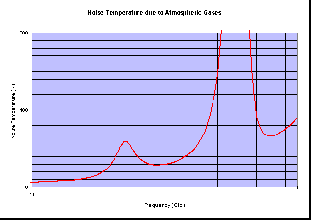
Gaseous loss does not just casue attenuation, it also causes noise. If you really want to the noise temperature can be calculated from:

Where T(l) is the temperature of the medium in K at point l, ![]() (l)
is the absorption coefficient and l is the distance along the path. This can
be simplified for long paths to:
(l)
is the absorption coefficient and l is the distance along the path. This can
be simplified for long paths to:
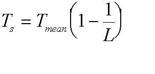
Where Tmean is the mean medium temperature and L is the path loss. Here it is as a figure:
© Mike Willis December 26th, 2006