The Fundementals
Introduction Maxwell's equations Plane waves Free space loss Gas Loss Refraction Diffraction Reflections Troposcatter Rain effects Vegetation Statistics Link budgets Noise Multipath Measurements Models
Beyond the Horizon
You might imagine waves travel along straight lines for ever, or until they
hit something. For a transmitter on the ground, any power radiated above the
horizon will go into space. Horizontally beamed signals will travel to the
horizon and then be absorbed, signals below horizontal will be absorbed or
scatter into space.
Rule of thumb – distance to radio horizon
(km) versus transmitter height (m) d = 4.12√h
We know signals do propagate beyond the horizon and the major mechanisms are:
Atmospheric
Refraction
To understand refraction, which is the atmospheric bending of the radio path away from a straight line, we need to remember Snell's law:

Willebrord Snel van Royen (1580–1626) was a Dutch astronomer and mathematician and is most famous for his law of refraction, which is now known as "Snell's law". In 1617 he reported on an experiment to measure the distance between Alkmaar and Bergen op Zoom which are separated geographically by one degree with the aim of determining the radius of the Earth. He measured one degree to be equal to 107.4 km, which was only 3km out. He also developed new method for calculating π. He discovered his law of refraction in 1621.
Refractive index vs Height
As we move to higher altitudes we have
lower pressures and lower temperatures. As a result the refractive index of
the atmosphere usually falls with height.
Radio waves get “bent” downwards and are able to propagate beyond the geometric
horizon, which extends range.
To find out how much, we need to know how the refractive index of air varies with height. This requires the introduction of a new "N" unit.
N - Units
The refractive index of air is very close to 1. Typically the refractive index n = 1.0003 at sea level and this is most tedious - there are lots of decimals that must be used because the fine detail is important, so we define a new unit, the "N" unit where:
N = (n - 1) x 1 000 000
N is typically 310 at sea level in the UK. The value of N can be calculated from this formula:
Where:
P = dry pressure, ~1000mb
T = temperature, ~300k
e = water vapour partial pressure ~40mb
The dry term depends only on pressure and temperature, the wet term also depends on the water vapour concentration. The temperature, pressure and water vapour pressure vary with time and space.
Pressure falls exponentially with height, the scale height, where it drops to 1/e of the sea level value is around 8km. (This value of e is not the water vapour pressure, it is the constant e from natural logs and has the value 2.718). Scale heights are used frequently in describing functions that decrease exponentially.
Temperature usually falls by 1oC/100m in the first few km above sea level.
Water partial pressure is much more complex, it is strongly governed by the weather and is limited to the saturated vapour pressure - the amount of moisture the air can hold. Once the temperature drops below 0C the excess water vapour condenses out as clouds. The saturated water vapour pressure is around 40 mbar at 300K (a warm day) and 6mbar at 273K (freezing). The height above the ground where the air temperature decreases to zero C is called the zero degree isotherm. It is typically at a few km in altitude, near the cloud base. Practically, in the UK climate, the amount of water vapour above 2-3km is negligible.
The result of al this is that the refractive index normally falls exponentially with height in a “standard” atmosphere. The scale height of the exponential is ~7.4km and as is shown below, in the first 1000m we can approximate this pretty well with a straight line with a slope ~ -40 N/km.
Representing an exponential function as a straight line is cheating, but it is a good enough approximation up to 1-2km or so. Beware of this cheat when planning systems on top of mountains.
Super-refraction
If dN/dh exceeds -157 N units, signals will be refracted by more than the
curvature of the Earth and be trapped. We call this super-refraction.
Why the -157 figure? To explain, recall that N typically falls by 40 units per km of height. We call this the lapse rate of N.
The rate of change of angle of the ray dθ/dh ~ dn/dh ~ dN/dh x106 which we find from Snell’s law and through applying the small angle approximation sin(θ)~tan(θ)~(θ) and
The radius of the Earth is ~ 6371 km. To just follow Earth curvature, dθ/dh
needs to equal the curvature of the earth, which is found to be -1.57x10⁻⁴
radians/km if you do the maths. Remember N units are a million x ( refractive
index - 1). So that is why dN/dh = -157 N units/km is the figure required
for a radio wave to just follow Earth.
The equivalent Earth radius
Many models are simpler if we can treat radio waves as if they were traveling
along straight lines in a standard atmosphere (dN/dh = -40)
We can achieve this by pretending the Earth has a larger radius which we call
the equivalent Earth radius Re.
We define the “k factor” k such that Re = k R. Typically
Re = 4/3 R in the UK, i.e. the k factor is 4/3.
Having done this we can then study paths for clearance by drawing straight lines rather than curves across a terrain profile. The ability to draw straight lines is practically, very important. It also simplifies propagation prediction software used in link planning. Nobody does it by hand any more. The image shows a path profile where line of sight is blocked. The red ovals show the Fresnel ellipsoids, in this case the first. These will be covered when we come on to study diffraction, but for a link to be line of sight, no-terrain should enter into this Fresnel ellipsoid.
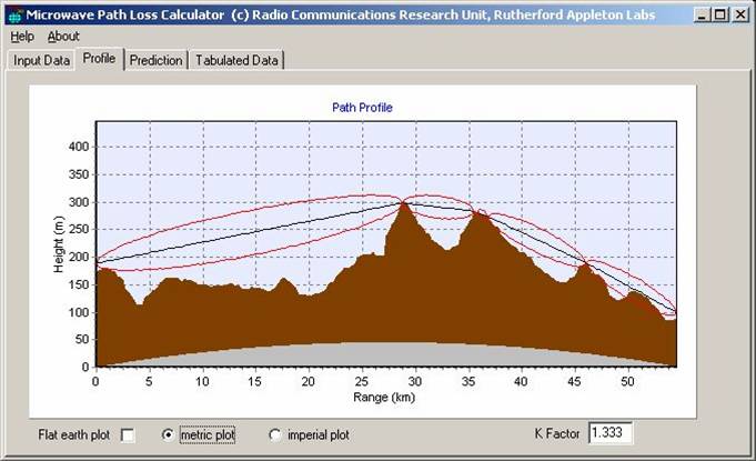
Example of a path profile
(note the red curves represent Fresnel zones, to be covered later)
Ducting and Inversions
Non-standard atmospheres can lead to anomalous propagation. Pressure tends to be quickly restored to an equilibrium, so the most important are variations in the water vapour concentration and temperature. Ducts tend to form when either Temperature is increasing, or water vapour concentration is decreasing, unusually rapidly with height. For example:
Ducts can occur either at ground level or be elevated. Depending
on the terminal height, the signal may or may not couple into a duct. To couple
into and remain in a duct the angle of incidence must be small, typically
less than 1o.
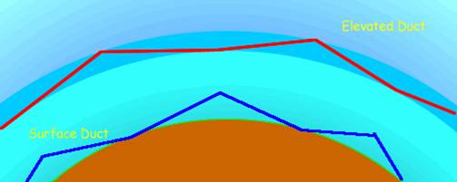
Duct depth and “Roughness” are also important. If the duct depth is small compared to the wavelength, energy will not be trapped. If the roughness is large compared to the wavelength, energy will be scattered out of the duct. Surface ducts have the ground as the lower boundary and energy will be lost to the terrain, vegetation etc.
Elevated ducts can allow signals to propagate for very long distances beyond the geometric horizon. It is possible for intermediate terminals to be below the elevated duct and not able to couple into it – resulting in non-monotonic path loss with range, rather similar to the skip zone at HF. A good example of the temperature inversion occurred on 7th November 2006. Strong inversions like this are unusual in the UK.
The refractivity profiles (http://weather.uwyo.edu/upperair/sounding.html) show a widespread sharp decrease in N with height. This gave rise to strong super-refraction and caused some interesting anomalous propagation effects with long range interference to services.
What causes conditions like this?
Causes of Ducting
Briefly the weather alters the temperature, pressure and humidity
of regions of air as they are moved about, mixed up, elevated and depressed
by cyclones and anti-cyclones, and are heated by the sun and cool down through
radiation at night. There are several major ducting mechanisms:
Evaporation Ducts
There is usually a region extending for a few metres above the surface of the sea where the water vapour pressure is high due to evaporation. This also occurs over large bodies of inland water, for example the great lakes. The thickness of this evaporation duct varies with temperature, typically it extends to 5m above the surface in the North sea, 10-15m in the Mediterranean and often much more over warm seas as in the Caribbean and Gulf. These ducts have a significant effect on Shipping and have been extensively researched. It is the reason that VHF/UHF propagation over sea can extend to great distances causing all sorts of international frequency co-ordination problems. It is also why you might want to get your warships anti-aircraft radar antenna nice and high.
Temperature Inversions
Usually, temperature falls with height by about 1 degree centigrade per 100m. On clear nights the ground cools quickly by radiation and this can result in a temperature inversion, where the air temperature rises with height. This happens when solar radiation during the day heats up the ground and the warm ground raises the temperature of the air near to it. This warm air rises as thermals. On clear nights the ground can cool very quickly, also cooling the air close to it. This results in the situation just after sunset where there is cool air close to the ground with warm air above it. This is a temperature inversion.
If the air is dry, the temperature term in the equation of N above becomes dominant and super refraction and ducting can occur. This is effect particularly common in desert regions.
If there is significant water vapour the relative humidity can quickly rise
to 100% and excess vapour condenses out as fog. This condensation reduces
the water vapour density near the ground. There is then cold dry air near
the ground, with warmer moister air above. This results in sub-refraction
which can lead to multipath on otherwise apparently perfectly good line of
sight links.
Subsidence
This is a mechanism that can lead to elevated ducts and is associated with
high pressure weather systems - anticyclones. Descending air that has been
forced downwards by the anticyclone heats up as it is compressed. Remember,
air pressure always falls with height so air that is descending must be compressed
and compressing air causes it to heat up. This descending air may become warmer
than the air below it, leading to an elevated temperature inversion. This
all happens at around 1-2km above the ground, which is too high to affect
anyone except highly elevated stations, as the angle will be too large for
a ground based station to couple into the duct. As the anticyclone evolves
the air around the edges subsides and this brings the inversion layer closer
to the ground. A similar descending effect can happen at night. In general,
the inversion layer is at its lowest close to the edge of the anticyclone
and at its highest highest in the middle. Anticyclones and consequently temperature
inversions, often exist over large continents for long periods.
Advection
This is the movement of air masses, typically occurring in early evening
in the summer when air from a warm land surface advects over the cooler sea.
This warm air mixes with the cooler air which will be relatively moist as
it is close to the surface of the sea. This then extends the height of the
evaporation duct and can cause high humidity gradients together with temperature
inversion that forms a surface duct within the first few 100m above the sea.
These ducts do not persist over land and are a coastal effect. Typically in
the UK they are associated with warm anticyclonic weather over the continent
of Europe and advection out over the north sea. They tend to be weaker than
subsidence ducts but they do occur relatively often over the North Sea and
can persist for many days. For example, it is relatively common for UHF signals
to propagate well beyond line of sight from the East coast of England across
the North Sea into the low countries.
The picture below shows what the ITU-R consider to be the global incidence
of ducting. It replaces an earlier model that only used Latitude.This really
does still need to be tested some more as it may be more of a reflection of
Matlab plotting routines for sparse data than actual reality. Use with care.
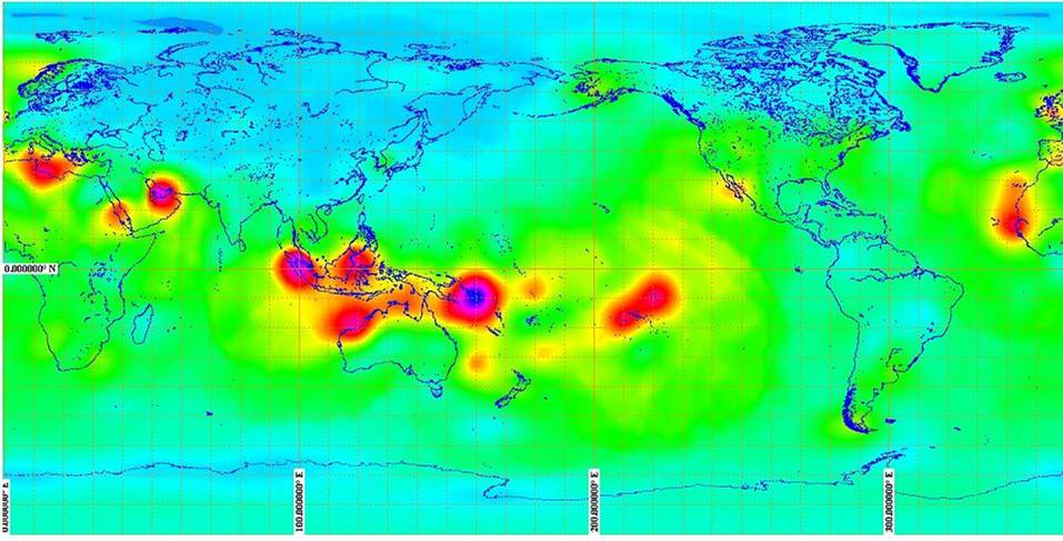
The original model was very crude:
Frequency of occurrence
Evaporation ducts - happen all the time around the UK and a widespread duct frequently forms over the sea. Surface ducts occur for around 6% of time, they tend to be up to 300m in height and cover ~100km. This is a fairly low incidence compared to other regions. Surface ducts occur for around 50% of the time in the Gulf, so they are not considered as anomalous in that region.
Elevated ducts exist for around 7% of time, they occur up to 3km in altitude,
and cover ~100km. Again this is low incidence compared to other regions Elevated
ducts happen for 40% of the time in Gulf.
© Mike Willis May 5th, 2007