The Fundementals
Introduction Maxwell's equations Plane waves Free space loss Gas Loss Refraction Diffraction Reflections Troposcatter Rain effects Vegetation Statistics Link budgets Noise Multipath Measurements Models
Reflections from surfaces and objects
The effects of reflections on the radio channel are very important in propagation studies. We will start off by looking at the simplest case of a reflection from a smooth flat surface of infinite extent. This is one of those cases that does not really exist, but as long as the surface is large compared to the size of the Fresnel zone, it will behave in the same way. Exactly what we mean by "smooth" we will come onto later.
Reflection from a plane
The phase and amplitude of the reflected wave is found from the reflection coefficient ρ. The value of ρ is different when the E plane or the H plane is parallel to the reflecting plane. The reason the expressions are different is because the surface has different properties for E and H fields, one governed by the permittivity, the other by the permeability.
Where ε = permitivity, σ = conductivity. Generally ρ is complex and both amplitude and phase change on reflection. Frequently substitutions are made for relative permitivity and relative permeability.
We define the relative permittivity εr = ε/εo
And for conductivity we use parameter x = σ/ωεoSome Typical Values:
Surface Dry Ground Average Ground Wet Ground Sea Water Fresh Water
Note if θ >> 0, sin(θ) >>0 so ρ >> 1
This is best illustrated by a picture which shows the magnitude of the reflection co-efficient. Note that the Brewster angle only occurs with Vertical polarisation. This is significant and finds practical use in polaroid sunglasses, which for example will cut down reflections from the road when driving into the sun.
For the signals to cancel, the phase shift of the reflected path needs to be a complete wavelength. The reflection gives a 180o phase change, for destructive interference we need a 180o phase change which we can get by adding a further 360o. That is the path needs to be one wavelength longer. For example, the path length difference can depend on the receiver height.
Doing the algebra and assuming d >> h  and
and 
The field strength can be calculated by adding the direct and reflected ray accounting for phase difference Δφ .
The power is proportional to the square of the field strength and for grazing incidence ρ = -1 so:
So for example with d =1km, htx = 10m, hrx = 1-10m, λ = 30cm we find signal strength lobing with height with a sine squared response.
Without an antenna moving up and down you might think this is unimportant as long as you avoid putting an antenna in the null, but it is. On long links, the change in refractive index of the air with the weather may move the nulls about vertically. There can also be multipath within the atmosphere itself via refraction leading to multipath cancellation - it is frequently the most important fading mechanism for microwave links below 10GHz. An example is shown below which was measured on a 60km 1.5 GHz link.
Usually, we do not think of the ground itself moving up and down relative to the antennas, this does happen though with the classic example being a path over an estuary. People receiving terrestrial TV over an estuary tend to need two antennas vertically spaced by a around a metre so that only one will be in a signal null at any given time.
The relative path length phase difference also depends on the wavelength and hence the frequency, so you may find nulls in the spectrum. This is a particular problem for broadband systems as where there is a reflection, there is likely to be a null somewhere in the spectrum.
Rough and smooth surfaces
A rough surface can be thought of one that gives diffuse reflections, like you might see from light reflected off a brick wall and a smooth surface as one that gives specular reflections, like looking in a mirror.
There is no hard transition from rough to smooth, it is a gradual process but that is not good enough for radio engineers, we need some form of criterion and the one we will use was developed by Rayleigh. It is based on the path length difference between "rays" reflecting off the surface. The term "ray" is a little misleading, we are considering a wavefront and it is really the amount of distortion of that wavefront that matters.
Taking ray A and Ray B above, the surface is considered smooth if the path length difference is no more than a small fraction of a wavelength. Specifically a surface is rough if the phase difference is less than 90o or π/2 radians. In our example above there is a different path length for both rays of 2dsin(θ) and the phase difference is this length multiplied by 2π/λ. Mathematically the phase shift is:
And if we define rough as a phase shift Δφ > π/2 a surface
is rough if:
Note that this depends on the angle of incidence, so to a wave arriving at a shallow incidence, a surface will appear smoother than head on.
Typically, roughness is described by the standard deviation σ of the surface around its mean level.
A constant is derived assessing the roughness in terms of σ:
The Rayleigh criterion is if C < 0.1 then we have a smooth surface. If C
> 10 then the reflection is so diffuse it can usually be neglected
For example, at an angle of 30o at 1.6 GHz, a rough surface has σ
of more than 3mm. At 5o it would be 1.8cm.
This criteria is also applied to reflectors used in antennas, for example a parabolic dish. The maximum useful frequency of the dish is usually taken as that where the deviation of the surface from an ideal parabola is just equal to 0.1 wavelengths.
There is no use making a dish antenna better than it needs to be, indeed, making a reflector from a mesh rather than as a solid has several practical advantages in terms of weight and wind loading. At 10 GHz 0.1 wavelengths is 3mm, so the modern satellite TV dishes a dishes which are perforated by 2mm holes still work almost as well as solid dishes.
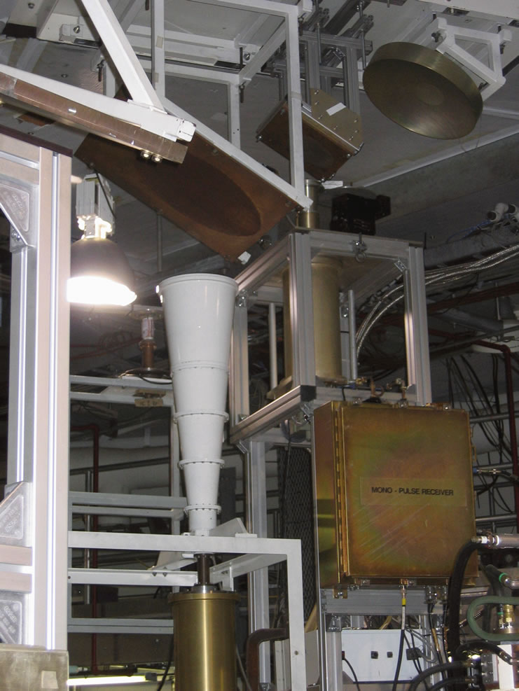
Dichroic reflectors
When is a reflector not a reflector? Take a piece of metal and drill holes in it, so it is mostly holes.
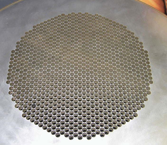
Depending on the size of the holes compared to the wavelength this is either a good reflector, or most of the energy will go straight through. What use is that? It is effectively a filter and a highly efficient one to use in the feed of a radio astronomy dish and can be used for splitting the beam of a beam waveguide into frequency dependant paths. Here are some in situ in the base of one of the 35m DSN antennas at Goldstone.
Fresnel Zones again
The principle of Fresnel clearance applies to reflection. Remember the first
Fresnel zone encloses all points where the additional path length is less than
λ/2. As a rule of thumb, reflecting object needs to be larger than 0.6
of the 1st Fresnel zone or there will be scattering loss. This becomes especially
important at longer wavelengths as objects behave more like scatterers than
reflectors.
© Mike Willis May 5th, 2007